Head in the clouds Posted October 1, 2017 Author Share Posted October 1, 2017 Gents, I have some comments on leak testing in this thread that may be helpful. I recently needed to leak test two wing tanks and the main tank for a Dakota Hawk I am building. I first used balloons filled with air (a safe low pressure test) and looked for bubbles. Aircraft grade Balloons and bubble liquid were bought from the local party shop. I found one very small leak. The chaps in the club were a bit sceptical about this test so I went back to the party shop for some helium filled balloons. ($1 each) I fortunately have access to a helium sniffer gun. This is a very sensitive method. The Helium molecule is small and if there is a path is will escape. It will pick up your breath if you don't brush your teeth. By this method I quickly found a second leak. On redoing the bubble liquid on the second leak, and knowing where is was, I could just see it. My conclusion is this. You can miss small leaks by immersion in a water bath (the supplier did). An air pressure test with bubble liquid is good but you have to go over every joint very slowly and carefully in order to see a small leak. Helium and a sniffer if you have access to it is the best. It also is a way of sometimes testing in position as the instrument probe has a long nose for sniffing and a small vacuum pump. The instruments voice gets squeaky (beeps) if it finds a leak in the vacinity. I made the mistake of not washing the bubble liquid off and it dried and it has marked the aluminium so there must be some chemical in there. I suggest you wash off with water immediately afterwards. Some excellent information there, thanks Brian! Just too late for me though, I completed the pressure testing of my tank a few weeks ago and have now installed it, so hopefully my method was suitably efficacious, time will tell I guess, when I first fill it up! By the way folks, some of you will have seen posts in another thread which reveal that BrianG is now the Australasian Rep for Oratex covering products. Since I am planning on using Oratex for DooMaw I had a long and very rewarding chat with Brian a few days ago, and he proves to be a most interesting conversationalist and all-round very knowledgeable fella. I highly recommend that anyone looking at a fabric covering exercise in the future get in touch with Brian via his website Wheelerswings ... but before doing that read your way through the website because there's a wealth of info about the product on there. Also, watch some of the videos and see how easy it is to apply, I was fascinated that the water-based paint-on-and-let-it-dry adhesive is activated at a lower temperature than the fabric shrinks, so you use a temperature controlled heat gun set below the fabric shrink temperature to get the fabric stuck on - and you can stick and unstick it to get rid of any wrinkles - then when it's all to your satisfaction you increase the heat of the gun or iron to tension the fabric. Simples! Even more amazing ... when you've got it all nice and tight you flail away at it with the sharp end of a claw hammer to show yourself just how damage resistant this stuff is - true! It's all in the video ... Another great tip from Brian is that the Oratex 6000, which is the heavier fabric (Oratex 600 for aircraft up to 600kg MTOW, Oratex 6000 for aircraft up to 6000kg) is only about 20% heavier, so for a bush plane which might get its tailfeathers dragged through the scrub on occasions, or have sharp stones flicked up by the tyres, you could happily use the (slightly) heavier fabric on vulnerable surfaces. And ... Brian is building a Fisher Flying Products Dakota Hawk. They're a truly lovely side-by-side two seater, all timber with geodetic construction for the wings and timber truss for the fuselage. Anyone considering building their own plane and who likes working with timber should have a good look at the Dakota Hawk. The plans are readily available and apparently very well drawn and complete, and there are some excellent build logs around (here's a great example of one being built by a lady in the USA) that would be a great help to anyone building their own. Perhaps we could persuade BrianG to document his build here? I'd love to see and read about the progress of another build. Brian is considering installing the D Motor, which I think is an excellent choice. 2 Link to comment Share on other sites More sharing options...
Head in the clouds Posted October 1, 2017 Author Share Posted October 1, 2017 October 2nd 2017. A quick catch up on the DooMaw log, I hadn't realised how long it's been ... last time I posted about it was a couple of months ago when I had just started the fuel tank welding and made up the aly skins for the front of the fuselage. I machined up a sump for the bottom of the tank with the drain set below the outlet so that any condensed water can be separated, welded that in along with several other fittings for fuel gauge, return lines etc, and the filler assembly which is located in the bottom right corner of the windshield similar to the Wittman Tailwind. It's there because, being a taildragger, that's the highest point when at rest on the ground. I completed the tank welding and then installed the on/off tap on the tank outlet and sealed off the various other tank openings. Using a compressor I pressurised the tank via the valve and closed it off once the tank had assumed the shape of a Michelin Man. From previous experience a tank without baffles goes that shape at about 3-4psi. It's important that the ambient temperature doesn't change significantly during the pressure test because as it gets warmer the pressure increases and v.v. so that would mess up your results. The first part of the test involves sitting the tank's largest side (the top in my case) on a flat surface and measuring the deflection caused by the bulging. Alternatively, if it's easier you can lay a metre steel rule (or any straightedge) vertically over the surface of the tank. Then use a vernier to measure the extent of the bulging of the surface. In my case it was 37.4mm. I left it in a stable-temperature air-conditioned room for an hour and then measured again. 27mm this time - uhoh it looked like we had a problem. Of course it could be just a leak at the shut-off valve, or the filler cap, or any of the fittings and/or hoses that were closing off the various penetrations for fuel gauge lines, return lines etc. Out with the bubble liquid and a brush and an all-over test revealed nothing anywhere. That was a bit of a surprise so I increased the pressure again and went over it all again, still nothing. Dug out a large composting container and filled it with precious water from the tank (no town water here and it hasn't rained for ages) and immersed the tank one side at a time and found the leak, a tiny pinhole where the start of one weld run had overlapped the end of a previous one without fusing properly. It was visible when revealed but I'd not been able to pick it from the post-welding visual inspection. A few seconds of welding later and the tank held pressure for six hours with no deflection change so I scoured the surfaces and painted it with etch primer. Two things worth noting about finding leaks using a waterbath - first, don't try and do it by immersing the tested weld too deep or the water pressure can exceed the low pressure in the tank and the air won't leak out, and second always put the flat surface being tested at an angle, not exactly flat, so that any bubbles from a leak on the underside run up the surface before coming to the surface, that gives tiny micro-bubbles time to join together and form larger bubbles which will be visible whereas the micro-bubbles can be very hard to spot. I made up the 3mm aly straps to mount the tank, had to modify the original cleats I'd fitted to the fuselage, a bit of touch-up paint and then installed the tank. Following that I could re-visit the plywood floors which needed a bit of trimming to get them in since I'd added a lot of cleats and fittings inside the fuselage since I originally made the floors. Then four more coats of water-based Cabothane Clear (great stuff that is!), installed the Rivnuts and screwed the floor down. Then I could start to look at the installation of the pedals before wifey reckoned winter was over and it was time to anti-foul our little sailboat and get it back in the water, hence the long delay since last post. Today is a public holiday and cloudy weather not at all conducive to messing about in boats so I'll be scouring the fuselage skins ready for a coat of etch primer. A few pics - Another 59hrs in that lot, making a total of 1662hrs so far. 2 Link to comment Share on other sites More sharing options...
Head in the clouds Posted November 4, 2017 Author Share Posted November 4, 2017 November 5th 2017. Time for an update or two - I scoured the fuselage skins as mentioned last post and then they sat on the bench covered with a tarp for four weeks waiting for a day when I had both time and suitable weather for spraying the primer on. That happened eventually and they're now on another bench awaiting the top-coat once I get the paint ordered. 4hrs in that for the log. Next it was time to start looking at mounting the engine. Some while ago I was fortunate to find a low-priced ring-mount advertised on the site here so I snapped that up. Originally I was going to use a bed mount as it has a few advantages, especially its forward structure which is handy for mounting the radiators but on the other hand it restricts access to the underside of the engine for maintenance and also gets in the way of the exhaust routeing so I guess it's a case of swings and roundabouts. It proved to be very fiddly to get the mount into position, I had to remove the wiring loom at the back of the engine, and also two of the ignition trigger units. At Bert flood's they say it can be done without that but I couldn't seem to find a way. Also, the left hand two elbows out of the water pump were set at an angle where their hoses clashed with the legs of the ring-mount, so they clearly had to be altered. A few phone calls to those in the know and I soon had the water-pump housing removed and carefully clamped in soft-jaws in the vise and the flame of the blow-torch carefully playing over the housing to soften the Loctite so I could rotate the elbows in their threads. It was a bit nerve-wracking, I didn't want to overheat the housing and warp it and neither did I want to put too much pressure on the elbows as they're very thin castings with a fine thread cut into them which further weakens them. Anyway, as soon as the housing was hot enough (very hot - probably around 150-180C) they moved quite freely. I ended up having to heat and adjust them at least half a dozen times. I was able to get the top left one set right quite easily but couldn't find any position at all which allowed the lower hose to miss the legs of the mount. Eventually I found and downloaded all the manuals for the engine, that included some I didn't know were available to we unwashed public ... the Heavy Maintenance Manual (for engine rebuilds rather than Line Maintenance), and the Illustrated Parts Catalog. The Parts Catalog revealed an elbow not fitted to my engine, of 80 degrees bend rather than 45 degrees, so I guessed that might be the answer to my problem. Bert Flood's agreed and had the new part available and it arrived by express the next day. All fitted and looking good now. There was some considerable difference of opinions about which Loctite to use to re-secure them, Floods, the Rotax manual and those who have completed the Heavy Maintenance Course with Rotax all had different answers, so I decided to go with the Rotax Manual ... except that particular Loctite number doesn't exist anymore. Further research revealed that all the Loctites in a particular class end up the same once cured, they're just different in the mode/method of application and the cure rate. So, I went with the 290 Wick-In type which was convenient because it is applied after screwing the fittings together and it migrates into the thread. It also cures slowly (24hrs for full cure), allowing plenty of time for fine adjustment. It's rock-solid now. Once the mysteries of the ring mount were solved I had to think about how I was going to attach that mount to the firewall frame incorporating the rubber universal mounts for isolating the vibration. The answer would be a similar ring mount with sockets for the rubbers, so I made up the parts, removed the ring-mount again to use as a jig and set it up on the bench for tacking. The pictures show the (white) ring mount being test-fitted to the engine, the problem with the water-pump elbows (on the left), and the first stages of making the isolation mount - Another 27hrs to that stage, making a total of 1697hrs so far. 1 Link to comment Share on other sites More sharing options...
Head in the clouds Posted November 5, 2017 Author Share Posted November 5, 2017 Once the isolation ring was fully welded out I had to mount it 'somewhere in free space ahead of the firewall' where it needed to be to correctly position the engine. It isn't square to the firewall either, since the engine has 2 degrees of right thrust and one degree of down thrust whilst at the same time keeping the drive hub/spinner centred at the front of the cowling bowl. Those off-angles result in the isolation ring being displaced sideways and upwards as well as being angled. Gladly, determining the actual position and angles for it were relatively simple using and measuring off the CAD model, so I was able to make up a very simple jig with a couple of pieces of timber, some threaded rod and some 'dummy' universal rubber mounts machined up from aluminium - I couldn't use the real rubber mounts because the weld heat would destroy them while tacking. It was around this stage that I decided that the airbox which provides filtered or heated air to both of the carburetors was just too much trouble to be entertained. It interfered so much with the straight-line path of the legs from the firewall hard-points to the isolation ring (see pics in previous post to see how much room and access space the airbox takes up). My first path was to phone as many folks as possible to ask them about their real experiences with carby icing, particularly in the warmer climes, since I don't have much intention of flying in the southern parts. The outcome was that while icing seems rarer in the north, it might still be an issue on occasions, and of course once is one time too many. Options other than the airbox are a system using the engine coolant flowing through a couple of castings pressed onto the carby throat that heat the carby rather than the air, which is more efficient of course, and there's an electric heater system also available. The coolant-based system is US$400 so it's AU$500 landed here - I did find another source US$100 cheaper but they were out of stock - and that seems quite expensive for a couple of small castings and some tubing and barbs. Also, it's a system that is always 'on' which is fine but being 'set and forget' there's always the possibility that it might not be working when you need it. The problem is that since its tube diameters are very small they run in parallel with the normal coolant flow, rather than in series with it and apparently some folks have discovered a lack of flow at times due to collection of air in that part of the system. I preferred the electric system but was not convinced that their way of doing it is the best either ... so I've come up with my own unique system which I'll describe in detail later. The upshot, though, is that I had determined that I could do away with the airbox altogether and that made access between the firewall hard-points and the isolation ring very much simpler. So - I have a complete airbox and filter/butterflies/drip trays assembly for sale if anyone needs one, it cost $1000 or more but it could be had for much less now ... Once I had the isolation ring positioned, and the parts for the mount's legs made, I could trial fit them and adjust the threaded rod to get the exact position for the ring, so that all of the leg parts fitted accurately. Then it was just a case of tacking them all together. Before I could complete the welding, though, I had to remove the assembly from the firewall hard-points for easier access while welding, and also so that I didn't burn the paintwork behind the ss firewall. If I was to weld out the whole frame after simply unbolting from the hard-points, the welding heat and shrinkage would pull the frame badly out of shape, so I welded scrap bars to the mounting lugs around the perimeter of the frame and one diagonally across as a triangulated bracing. It all worked out well, when I re-installed the frame after welding the holes lined up within a millimetre or so and could easily be pulled exactly over the holes for bolting. Once I'd checked that I cleaned it all up and sprayed it with 2pak epoxy ready for the engine installation. Another 39hrs making a total of 1736hrs so far. 3 1 Link to comment Share on other sites More sharing options...
Oscar Posted November 5, 2017 Share Posted November 5, 2017 Great to see you back on the case, HITC!. And - as always - the pictures of your construction work are, to me, both a joy to look at from the excellence of structural integrity and humbling for the quality of your work. Any tube-frame structure looks to be really simple, BUT to get the force lines being taken out absolutely concentrically to the tubes and properly resolved through the projected lines through the centre of a join in a multiple-angle, multiple-tube joint cluster is work bordering on the mystical and arcane, for most people other than those deeply immersed on this sort of work. I've only done a couple of mounts ( a Jab. 2200 into a Motor-Falke, and an engine test cell mount for Jab. engines) and the time, patience and occasional wasted tube I had to expend on those, gives me huge respect for your stuff. I reckon you'd get a tick of approval from Barry Manktelow anytime. Anybody who reckons that it'd be easy to just hang the engine out the front where you want it to end up, and then cut and weld tubes to make that actually happen, has never tried it. Having recently made up an airbox for my Jab. project, I am most interested to see what you will come up with as an alternative to what - I assume - was a standard Rotax airbox? If it IS a standard Rotax airbox, to me (only from looking at your piccy of it), it has a monumental deficiency in terms of meeting the FAR requirements ( not necessary for an Experimental, of course, but still worthy of noting as an operator..) The FAR requirement for an airbox requires not just to provide heated air (I think from unreliable memory, it's a 20C air temp rise over ambient but don't jump on me if I am wrong here) when selecting 'carby heat', but also to provide an alternate inlet tract path in the case of blockage of the air filter. That might sound unlikely - but in Australian conditions, you could get that from a take-off in bulldust / heavy chaff from a recently stripped wheat paddock/ grasshopper swarm, for instance. Or a dead budgie sucked onto the inlet scoop.. Probably not problems anticipated in operation in a European environment. The FAR requirement is for the hot air intake to bypass the filter. I assume that this has been predicated on the idea that hot air is only pulled when in flight, where the air filter is pretty much unnecessary. My airbox meets that requirement - the original Jab. one in my very early Jab. did not - and it was a PITA to achieve it. I think all later Jab airboxes DO do it. With the Bing carbies used on both Rotax and Jab. engines, it is also important to have the carby balance tube intake(s) situated where switching to hot air doesn't screw up the balance air. When doing the certification tests for the Gazelle, a family member found that pulling hot air reduced the full-power revs by over 2K - if climbing out and the filter had blocked enough to collapse under full-power load, the thing would have mushed to a crash. Further work on that got the revs. drop to less than 200, (again,from memory - may have even been less than that). Just throwing on a pair of filters upstream of the carbies on a Rotax, will work fine - until they don't. At which point, I suspect, life becomes 'interesting'. Link to comment Share on other sites More sharing options...
NinjaNate Posted November 5, 2017 Share Posted November 5, 2017 Hi HITC All I can say is wow!! I have just spent an entertaining hour long read of your build log as I sat on my back deck this afternoon on a typical balmy gold coast Sunday. From start (way back on June 15) till your last entry today I've been impressed by your meticulous build approach and I've thoroughly enjoyed reading your decision processes and learnings. Very impressive. I cant wait to see the final product on here, but not nearly as much as you I'm sure. Nate 1 1 Link to comment Share on other sites More sharing options...
Head in the clouds Posted November 18, 2017 Author Share Posted November 18, 2017 November 17th 2017. Well, I just had one of the most stimulating days during the whole of my project. Our well regarded forumite, Old Koreelah, needed to travel up this way for family matters - and I am so delighted that he accepted my invitation to call in and say G'day. What an interesting person and fascinating conversationalist he is. We chatted non-stop through a multitude of subjects ... I'm still mentally re-living it. If any of you have the chance to meet up with him I guarantee you'll enjoy and value the time spent. And - this was so very welcome following what I unfortunately found to be the least enjoyable part of the DooMaw project so far - building the exhaust system. Some will recall my previous project, the AussieMozzie, described in the first posts of this thread, and that was when I bought the 912ULS engine I'm using in DooMaw. For AussieMozzie I made extensive changes to the standard 912 exhaust and now, using it for DooMaw, I had to change it all back to the original setup, or pretty close to that. At the best of times I dislike welding stainless, and my cheap chinese copy of a good TIG welder is not the best for welding thin material, let alone stainless which just slumps to the other side of the material at the first hint of heat. Generally that wouldn't matter, but if you get lumps of slump all around a butt weld of exhaust pipes somewhere in the middle of a length of the feed pipes ... well you have a major exhaust flow restriction which means a permanent performance reduction for your engine. I re-used as much as I could from the previously-made AussieMozzie exhaust system, although most of that had slump/restriction problems but I made a set-up for the milling machine where I could run dressed mounted stones into the tubes and grind away the internal restrictions ... all nice and clean. Then the only potential issues were where tubes were joined in the middle, so I just accepted a small weight penalty and used thicker walled tubes and welded them with very gentle stop-start welds like a series of tacks. It all worked out and the exhaust system is fine though I still say it's the most unpleasant part of the project ... But .. the unpleasant aspect isn't just because of the demands of the welding. There just isn't any room for tolerance in the length of each of the manifold tubes. Making the first tube is easy enough ... as long as you start with the one that is most critical to the final position of the muffler. I worked that out in advance and started with the rear left cylinder. That worked fine though it took me a day and a half to get the pipes and spring hooks cut and tacked, then the rear right cylinder might have appeared simple but it wasn't, it took me two days to do that one. I was fairly happy that the front right would be easier, as it was, another day for that one, but I was stressed about the last one because there's simply no adjustment available for that one. Either you cut the tubes perfectly with no gaps, and weld them without pulling them out of shape, or it won't fit at all, or will have gaps that leak exhaust gases, and wear the muffler sockets. Anyway, concentration paid out and the end result is good but I'm sure there must be easier ways to build an exhaust system. Next challenge is the mounting of oil cooler and coolant radiator ... Another 40hrs, for a total of 1776hrs so far. 2 Link to comment Share on other sites More sharing options...
SDQDI Posted November 18, 2017 Share Posted November 18, 2017 Well that is the first time I have ever heard of old K as 'well regarded' but on a serious note the build is looking awesome HITC and I look forward to catching up with old K when he gets back to try and glean even more out of him about it all:thumb up: 1 Link to comment Share on other sites More sharing options...
Kyle Communications Posted November 18, 2017 Share Posted November 18, 2017 Allan just another beautifull job. I feel your pain. A year or 2 ago I converted a std rotax muffler which I had to add a bit in the middle of to make it fit the ring mount and into the existion cowl for the Sav. I had a gun welder mate doing the job for me but it was a mission and a half. I can understand why people whinge at the cost of getting exhaust systems done for these. The pipes from the headers were they from the original exhaust?...My original supplied had doughnuts done from ICP so I had to get some and use them..did you bend the header section or was it original? I really enjoy watching your work being done...just masterful 2 1 Link to comment Share on other sites More sharing options...
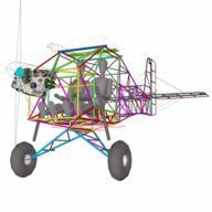
Marty_d Posted November 18, 2017 Share Posted November 18, 2017 Magnificent work (as always) HITC. There's only one problem that I can see... that green & blue fuselage skin looks a bit loose... 1 Link to comment Share on other sites More sharing options...
Head in the clouds Posted November 19, 2017 Author Share Posted November 19, 2017 Allan just another beautifull job. I feel your pain. A year or 2 ago I converted a std rotax muffler which I had to add a bit in the middle of to make it fit the ring mount and into the existion cowl for the Sav. I had a gun welder mate doing the job for me but it was a mission and a half. I can understand why people whinge at the cost of getting exhaust systems done for these. The pipes from the headers were they from the original exhaust?...My original supplied had doughnuts done from ICP so I had to get some and use them..did you bend the header section or was it original? I really enjoy watching your work being done...just masterful Hi Mark, thanks for the very kind words! What happened was that when I built the exhaust for AussieMozzie, the muffler was hard-mounted to the fuselage and set vertical so I had to move two of the muffler inlet sockets to the other end, so all four sockets were at one end of the muffler, the opposite end from the tailpipe. Then I made up the pipes from the heads to the muffler before realising that wouldn't work because the engine could move on its rubber mounts but the muffler couldn't ... so ... I cut each of the pipes and added another set of the flared cups and balls and retaining springs into each pipe i.e. each pipe from the cylinder head to the muffler was in two pieces instead of one, so that extra flexibility allowed the engine to vibrate independent of the muffler. The point of telling that is that I used up the donut-type bends and also needed more bends so I got them from a local tube-bending works. They're a lot heavier than the originals though. The original is 30mm x 0.9mm tubing but I couldn't find any of that in Oz so the new ones are made from 32mmx1.6mm, quite a bit of weight penalty but at least it's a bit easier to weld. I'm really enjoying watching your progress on Mabel too, you're making a wonderful job of it - and I hope you're getting over that bug. Link to comment Share on other sites More sharing options...
Oscar Posted November 19, 2017 Share Posted November 19, 2017 November 17th 2017.Anyway, concentration paid out and the end result is good but I'm sure there must be easier ways to build an exhaust system. Another 40hrs, for a total of 1776hrs so far. Having done a few for my racing car projects, I can confidently say - they ARE a bugger to do by hand.. I tried all sorts of tricks to get some heat-sink on the inside to minimise the 'spurts' of metal - none worked well. Sequential 'spotting' with a MIG with 'spot'-capability is a possibility, but though I have such a beast, I've never tried it on tube joins. Your result looks very damn good to me. Of course, there IS an easier way.. Here's one: All you need is a large supply of titanium tube and all the robotic fabrication capability of Honda Corporation! And a casual budget running into the multiple $Ms for the project. Easy as... 1 1 Link to comment Share on other sites More sharing options...
Old Koreelah Posted November 19, 2017 Share Posted November 19, 2017 November 17th 2017.Well, I just had one of the most stimulating days during the whole of my project. Our well regarded forumite, Old Koreelah, needed to travel up this way for family matters - and I am so delighted that he accepted my invitation to call in and say G'day... Very nice of you to say that, HITC. I thoroughly enjoyed my visit- and we didn't even get to talk about Nhulunbuy! Your STOL project is impressive, as are your wildlife mates. Well that is the first time I have ever heard of old K as 'well regarded'... There's always someone there to keep a bloke from developing an ego! 1 Link to comment Share on other sites More sharing options...
SDQDI Posted November 19, 2017 Share Posted November 19, 2017 It may be a little of my jealousy showing through Old K, just wishing it was me up there visiting HITC so didn't want you to feel too happy:sad angel: 1 Link to comment Share on other sites More sharing options...
Old Koreelah Posted November 19, 2017 Share Posted November 19, 2017 It may be a little of my jealousy showing through Old K, just wishing it was me up there visiting HITC so didn't want you to feel too happy:sad angel: I could give you directions to his place- I always wanted to tell you where to go! Link to comment Share on other sites More sharing options...
Oscar Posted November 19, 2017 Share Posted November 19, 2017 I could give you directions to his place- I always wanted to tell you where to go! Gentlemen: retire to neutral corners... 1 Link to comment Share on other sites More sharing options...
Head in the clouds Posted December 2, 2017 Author Share Posted December 2, 2017 2nd December 2017 Real work is getting in the way again, so progress has been a bit slow. I built the oil cooler mounting bracket, fabricated and welded up out of aly angle. I loosely copied the oil cooler/coolant radiator setup of the Foxbat but didn't end up liking the cramped location of the oil cooler tight under the spinner, where it has to be to allow enough room for the coolant radiator below it. Then I saw in the Rotax installation manual that the oil cooler is required to be below the oil pump, which isn't the case for the Foxbat but they seem to get away with it. I also didn't like the inlet/outlet being at the bottom of the oil cooler, it seems to me that there'd be a likelihood that the oil could just enter and exit in the bottom part of the cooler and it might never be filled with oil, especially since it is on the suction side of the oil circuit. Anyway, I threw out that mounting hardware and started again. This time I have plenty of space to play with, the oil cooler is up the right way, the hoses aren't perilously close to the exhaust pipes, and the coolant radiator will be mounted vertically into the port side of the cowling. That'll appear a little unconventional but makes a lot of sense in terms of keeping the coolant hoses short and away from the exhaust headers, and the radiator will still be in good airflow whether flown with the engine cowling on or off. Now it's time to get what will hopefully be the last hardware orders in from the US, so I'm having to spend time going carefully over the whole project to determine every missing bolt, nut, clevis pin, bearing and all the rest of it. By the way, does anyone reading this have any experience with the water-based Stewart covering system? Until yesterday I had every intention of, and was looking forward to using Oratex, until I calculated the amount of fabric I need and priced it up along with the special tools required. It worked out to be more than triple the price of conventional dacron covering and coatings, so although I haven't completely given up the idea I'm also investigating other options - hence the question about the Stewart system which avoids the use of flammable coatings and dangerous goods freight costs. Pics of the oil cooler setup - 11 hours for the log making a total of 1787 so far. Link to comment Share on other sites More sharing options...
Old Koreelah Posted December 2, 2017 Share Posted December 2, 2017 ...does anyone reading this have any experience with the water-based Stewart covering system?... Neat-looking oil cooler. Our club member who imports SuperStols gave me the last of his Polyfibre chemicals. He's totally sold on the Stewart water-based system and the finish on his latest one is impressive. Link to comment Share on other sites More sharing options...
Oscar Posted December 2, 2017 Share Posted December 2, 2017 HITC - class work, as always. I think you may be well served by moving the O/C away from the spinner. The advice given to me is that in the immediate area of the spinner, you tend to get small/negative air pressure due to the separation of prop-blast air around the cowl (sort of like an inverse venturi, I suspect) and immediately behind the spinner you will get reverse airflow past the shaft out to the spinner edge at least. Link to comment Share on other sites More sharing options...
Blueadventures Posted December 2, 2017 Share Posted December 2, 2017 2nd December 2017Real work is getting in the way again, so progress has been a bit slow. I built the oil cooler mounting bracket, fabricated and welded up out of aly angle. I loosely copied the oil cooler/coolant radiator setup of the Foxbat but didn't end up liking the cramped location of the oil cooler tight under the spinner, where it has to be to allow enough room for the coolant radiator below it. Then I saw in the Rotax installation manual that the oil cooler is required to be below the oil pump, which isn't the case for the Foxbat but they seem to get away with it. I also didn't like the inlet/outlet being at the bottom of the oil cooler, it seems to me that there'd be a likelihood that the oil could just enter and exit in the bottom part of the cooler and it might never be filled with oil, especially since it is on the suction side of the oil circuit. Anyway, I threw out that mounting hardware and started again. This time I have plenty of space to play with, the oil cooler is up the right way, the hoses aren't perilously close to the exhaust pipes, and the coolant radiator will be mounted vertically into the port side of the cowling. That'll appear a little unconventional but makes a lot of sense in terms of keeping the coolant hoses short and away from the exhaust headers, and the radiator will still be in good airflow whether flown with the engine cowling on or off. Now it's time to get what will hopefully be the last hardware orders in from the US, so I'm having to spend time going carefully over the whole project to determine every missing bolt, nut, clevis pin, bearing and all the rest of it. By the way, does anyone reading this have any experience with the water-based Stewart covering system? Until yesterday I had every intention of, and was looking forward to using Oratex, until I calculated the amount of fabric I need and priced it up along with the special tools required. It worked out to be more than triple the price of conventional dacron covering and coatings, so although I haven't completely given up the idea I'm also investigating other options - hence the question about the Stewart system which avoids the use of flammable coatings and dangerous goods freight costs. Pics of the oil cooler setup - [ATTACH]52873[/ATTACH] [ATTACH]52874[/ATTACH] 11 hours for the log making a total of 1787 so far. Looking great HITC. Just for info only; if your need a lower bend in the cooler outlet to oil can pipe elbow, floods sell another type that is a shorter stand off. It's in the parts book. I finished up getting them as it was better for my installation to keep the hose lower to get under the gear box housing. Cheers Mike Link to comment Share on other sites More sharing options...
Old Koreelah Posted December 2, 2017 Share Posted December 2, 2017 HITC - class work, as always.I think you may be well served by moving the O/C away from the spinner. The advice given to me is that in the immediate area of the spinner, you tend to get small/negative air pressure due to the separation of prop-blast air around the cowl (sort of like an inverse venturi, I suspect) and immediately behind the spinner you will get reverse airflow past the shaft out to the spinner edge at least. I'd agree Oscar, but that oil cooler is so large it may not matter much. Mine is the much smaller Jab original and I've had to tape over about 60% of it to get the oil temp up to 90C. 1 Link to comment Share on other sites More sharing options...
Head in the clouds Posted December 2, 2017 Author Share Posted December 2, 2017 Thanks for all the info folks. OK, great to have some feedback about the Stewart system, really appreciated. Also, what you say about the size of the oil cooler is taken on board, I have a friend who has lots of experience with this and he said he has to tape over most of his oil cooler in winter and about half of it in summer. But then he's in Tassie these days ... So I'm quite happy to have a large cooler, can always restrict airflow to it but it may well come in handy on a 40+ degree day outback. Good point about the reverse airflow Oscar, thanks, I hadn't actually thought that through but it just didn't 'seem' right where I had it at first. Thanks for the info about the smaller elbow Bluead, I did think this one was rather bulky but in the new position it fits rather well to run the oil hose between the coolant hoses and the pushrod tubes, so it'll do well at this stage. Link to comment Share on other sites More sharing options...
ClintonB Posted December 2, 2017 Share Posted December 2, 2017 I found the Stewart systems gear good on the Bushbaby repair areas after watching all of their Youtube vids to see how to prep, apply and paint-much better than reading about it. Seems to go a long way too.Only thing I would do different next time is use a flex agent in paint( I used PPG auto paint,) I have found that it cracks whilst working inside the airframe and bumping fabric. Link to comment Share on other sites More sharing options...
Head in the clouds Posted December 2, 2017 Author Share Posted December 2, 2017 I found the Stewart systems gear good on the Bushbaby repair areas after watching all of their Youtube vids to see how to prep, apply and paint-much better than reading about it. Seems to go a long way too.Only thing I would do different next time is use a flex agent in paint( I used PPG auto paint,) I have found that it cracks whilst working inside the airframe and bumping fabric. Hi ClintonB, thanks for your feedback! Yes, everything I've read suggests that the main reasons top coatings crack is due to lack of sufficient plasticisers (given that it's applied to a flexible fabric, rather than a steel auto body panel or house exterior, for examples). As I understand it from their documentation, the Stewart System's own topcoat contains plasticisers that, once cured, leave it looking 'glossy, almost wet' on the surface. A couple of people have suggested that's right. I guess it's everyone's choice of which topcoat to use, because the Stewart filler coat apparently provides all the fabric sealing/filling required, as well as the most important UV protection. After that they offer a topcoat that isn't cheap at US$338/gallon but those who have used it seem to recommend it. On the other hand polyurethane topcoats are about 1/3 their price and are known to be flexible (one can add more plasticiser if you like) and PU is very 'tough' and high gloss as a surface coating. So - thanks for all your contributions and I'm very much still open to more info please folks ... Link to comment Share on other sites More sharing options...
Head in the clouds Posted January 10, 2018 Author Share Posted January 10, 2018 It's more than a month since the last log update, though plenty has happened since, so it's time to catch up. Last log entry was about the installation of the oil cooler at the beginning of December. Following that I realised that if I wanted to have sufficient materials to work with over the Christmas/New Year break, I'd need to get some orders worked out and processed. It took me two long days to work them out exactly, including all the bolts I could think of, various heat shroud materials for hoses close to exhaust pipes, bearings, rod-ends, the rest of the brakes components plus plenty of spares for ongoing maintenance and all that. So I got an order off to FBI (Black Max brakes) and they were excellent, the order processed in two days and on my doorstep five days later by USPS. The weaker Aussie dollar this time made it a bit hip-pocket painful with the components this time coming to AU$800 and the postage AU$160, but at least I just stayed under the GST threshold so that helped. The Aircraft Spruce order took a little longer, a week before it was despatched and twelve days to arrive, but it was right in the middle of the Christmas postal rush, so that wasn't too bad, almost exactly the same price as the Black Max order. The third one was a bit of a misfortune in some ways. I mentioned previously about the shock of the cost of the UL600 Oratex fabric, BrianG the Australian representative had said he'd try and get a better price but I hadn't heard from him two weeks later so I guessed he couldn't do anything about it, so I went ahead and ordered fabric from Aircraft Spruce. The non-certified dacron is about $7/m compared to Oratex at $140 IIRC so that's a massive difference, but of course you then have to seal it, UV proof it and paint it. So I ordered the Stewart System adhesive and coatings, except the topcoat which added another $800 including freight and arrived in just four days from placing the order - awesome service! Just after I'd ordered the fabric and coatings the Oratex rep came back to me saying that the factory in Germany had found some seconds fabric which was perfectly OK structural but had a slight unevenness in the colour, and that I could have that at about a third the price. I wished I'd heard about it a few days earlier but it was too late by then. Even so it would still have been double the price of the other, and I'd still have had to buy the topcoat paint to paint the metal skinned parts of the airframe. I also did my research for the primer, undercoat and topcoat and a friend in the industry found me the best quotes, about $700 for all of it, so that's not too bad for a three-colour system. The coatings research and discussions took another full day, so that's another 24hrs of associated work but I haven't included any of that 'admin' or design time in the build log, so it remains at 1787hrs so far. 1 Link to comment Share on other sites More sharing options...
Recommended Posts
Create an account or sign in to comment
You need to be a member in order to leave a comment
Create an account
Sign up for a new account in our community. It's easy!
Register a new accountSign in
Already have an account? Sign in here.
Sign In Now