Bruce Tuncks Posted December 7, 2017 Share Posted December 7, 2017 The tiny rudder and fin make my old sk jabiru look funny when next to a new J170. It would be possible to add about 70mm to the trailing edge of both the rudder and fin without adding too much weight. Weight here does not only effect the c of g but it can also lower the rudder flutter speed. But it would make the plane more directionally stable, i hope. Anybody know what would be the result ? Link to comment Share on other sites More sharing options...
Oscar Posted December 7, 2017 Share Posted December 7, 2017 Bruce: be careful if adding any chord to either surface. When transplanting a UL ( or J120) fin and rudder to my ST1, I found the rudder was a very poor fit to the rear of the fin and modified it to be a better fit. HOWEVER, when doing that, I was advised strongly by an aero-engineer who had done the test flying on the early Jabs. for Certification purposes, that the maximum safe c.g. change to the balance of the rudder should be no more than a 5% rear shift behind the hinge-line. I would imagine that much the same rule of thumb would apply to the elevator. 1 Link to comment Share on other sites More sharing options...
Yuri Gagarin Posted December 7, 2017 Share Posted December 7, 2017 The tiny rudder and fin make my old sk jabiru look funny when next to a new J170.It would be possible to add about 70mm to the trailing edge of both the rudder and fin without adding too much weight. Weight here does not only effect the c of g but it can also lower the rudder flutter speed. But it would make the plane more directionally stable, i hope. Anybody know what would be the result ? Be careful with changes to control surfaces http://eaerofab.com/MooseForSale/SummaryDoc.pdf 1 1 1 1 Link to comment Share on other sites More sharing options...
Yenn Posted December 8, 2017 Share Posted December 8, 2017 Bruce. How does your Jab fly? Does it need extra rudder control? If yes then is it different from all the similar model Jabs, if so, maybe it needs attention. If it doesn't have a rudder control problem, do you think that changing things will be an improvement. From your question you are not sure of your ability to design any change, but I would warn you against accepting advice from others who may well have less ability than you do. I would think that a tiny rudder would be an advantage, having less drag than a bigger one. 1 1 Link to comment Share on other sites More sharing options...
Bruce Tuncks Posted December 8, 2017 Author Share Posted December 8, 2017 Thanks guys. The Jabiru actually flies ok, but it is not very directionally stable, certainly a lot less so than the J170. The skid ball is much more likely to drift off center. This is the thing I was hoping to improve. The rudder area in the SK is half that of the J170. So the factory must have considered it a good modification to make. I also notice that the SK rudder has no mass-balance at all. I don't know how to calculate flutter speeds, but adding chord would lower this speed for sure. Hopefully, a small amount of extra weight would not lower the flutter speed so that it would be close to the red-line 116 knots. The idea of adding to the trailing edge came to me when I was looking at adding a few inches chord to the leading edge of the tail fin. This would be possible, but a lot more work than extending the trailing edge. Link to comment Share on other sites More sharing options...
Oscar Posted December 8, 2017 Share Posted December 8, 2017 Bruce: if you are looking for more directional stability in cruise rather than just pure rudder authority, you need to be very aware of the interaction between vertical area and dihedral. In the case of my aircraft, with a significantly increased fin and rudder area, it will require more dihedral - so we are planning adjustable test lift struts and ultimately, new struts once the flight testing has determined the ideal amount of dihedral. Flight testing is the only real way to get the balance right! Get that balance wrong, and you end up with an aircraft with a harsh Dutch-roll motion. Jabs - LSA55s especially, and I think the SK has the same fuselage length? may wander a bit, but they sort of waddle along without making you airsick. Too much dihedral is ALSO lousy for motion in cruise; I've flown in a Rallye, which was a like a pig chasing truffles at the gallop in cruise. Seriously - sitting in the RHS beside a CASA-approved Test pilot, I had to do the navigating because he couldn't afford to take his eyes off the horizon lest we both barfed.. A minor addition of rudder area shouldn't produce any major changes, but if you increase it substantially, I seriously suggest you are embarking on a journey of chasing your tail ( pun intended, there!). May I politely suggest that before you attack the rudder with 'glass - try gap-sealing it. A brush-type seal might improve things for little effort 1 Link to comment Share on other sites More sharing options...
Mike Borgelt Posted December 9, 2017 Share Posted December 9, 2017 More fin area, same dihedral makes the aircraft spirally unstable. This generally isn't a problem. Most gliders are like that. Too much dihedral, too little fin area and the aircraft tends to dutch roll. You've seen this with free flight models Bruce. Make the fin too large and it is impossible to trim and will always spiral into the ground. Dutch roll is OK there. Hence the usual large amounts of dihedral. Why not just increase the fin area with a glove on the leading edge of the fin? Unless the rudder lacks authority I'd leave it the same size. Then no mass balance issues. Increasing the rudder area will require feet on the pedals or strong centering springs, otherwise the free floating rudder will not add to yaw stability. Oscar's suggestion about a gap seal is probably good too. Can you fit a glider type Mylar seal externally or a folded one internally? Yeah, I'm a flying qualities enthusiast. I'm astounded at what people will put up with. 1 1 Link to comment Share on other sites More sharing options...
Bruce Tuncks Posted December 11, 2017 Author Share Posted December 11, 2017 Thanks guys. I had avoided flying a J170 for years because I didn't want to know if it was better than my faithful old Jab. One day, my no.1 son said that he had advised this guy to get a Jabiru instead of this Rotax Russian thing. He said to NOT take him for a fly in my Jabiru cos that would put him off Jabirus for sure, but to arrange for him to fly in a club 170. So recently I did fly in a 170 and found it to be halfway between my old SK and a 747. This is what has triggered off my desire to improve some of the shortcomings of my Jabiru. I will look at hot-wiring a polystyrene leading edge extension for the SK. It should have a concave match for the existing fin LE and be capable if being glued/taped on for a test flight. About 3 inches more chord I reckon. Link to comment Share on other sites More sharing options...
Mike Borgelt Posted December 11, 2017 Share Posted December 11, 2017 I'd give it 2 or 3 layers of 110 cloth and epoxy on top of the hot wired foam and run them back a reasonable distance onto the fin skin and secure there with good double sided tape and tape over the top. You DO NOT want the extension to move sideways or partly fall off when you sideslip. 1 Link to comment Share on other sites More sharing options...
Oscar Posted December 13, 2017 Share Posted December 13, 2017 Bruce: Mike Borgelt's comments above are good advice in my opinion. If I were doing this, I would certainly clad the foam in several layers of 100-120 gsm glass - for several reasons, and the least of these is: you won't get anything that will securely adhere the foam to the fin. About your best alternative would be wrapping the foam in strips of aluminium tape, carried at least 50-75mm aft of the end of the foam. However, if I may add a few ideas.. Whatever you end up with, should NOT introduce any form of 'step' between the foam and the fin. If it does, there will very likely be flow separation over the 'lift' side of the fin causing it to prematurely stall, and your rudder become no more than a drag device.. not very efficient, and very non-linear in response to small rudder inputs. If you add the foam as the former, then add the glass skin (obviously, using PVA blue on the fin for separation..), then when if has all gone off, glue the resultant mod. to the fin with epoxy only on the 'extension' of the glass beyond the foam, you can remove the whole lot with a heat gun. Or, perhaps, use aluminium tape, which is very thin and sticks like sh!t to a blanket to a degreased surface. If you were to use duct tape to attach the mod.: from experience, the adhesive tends to go very soft at around 30C ambient. There may be higher-performance versions.. If you choose to use duct tape as the attachment medium - may I suggest: test fly in nothing more than about 20C ambient. FWIW: the 'limit load' on an LSA55 fin+rudder, is about 72 kgs. at a moment of around 800 mm above the fuselage cone ( I'd have to look up the test we did on my aircraft to be sure of that figure, but it's in the ballpark). The fin does bend - a little - at limit load. 1 1 Link to comment Share on other sites More sharing options...
Mike Borgelt Posted December 13, 2017 Share Posted December 13, 2017 Anyone happen to know what the airfoil on the fin is? Jab airfoils on the fin look kind of " round at the front, with kind of flat" to the rudder. If so it is unlikely to be a laminar flow section and will likely go turbulent about where the "step" is for this test attachment. I often see confusion between turbulent and separated flow. Near the leading edge the flow is usually laminar and it will transition to turbulent ATTACHED flow at the slightest provocation (bugs, waviness, deliberate turbulators, steps etc). The flow will separate on the upper surface when the angle of attack is large (around 15 degrees). Turbulent flow actually can help delay separation as the velocity profile in the boundary layer is such that there is more energy close to the airfoil surface. In some gliders the flow on the lower surface of the airfoil is deliberately turbulated somewhere in the 80 to 90% chord region the prevent the formation of laminar bubbles where the laminar flow separates and forms a bubble of circulation which results in a thicker turbulent boundary layer downstream of the bubble. The thickness of the boundary layer and its velocity profile at the trailing edge determine the profile drag of the airfoil 1 1 Link to comment Share on other sites More sharing options...
Old Koreelah Posted December 13, 2017 Share Posted December 13, 2017 I greatly improved the low-speed handling of my home built by adding a 30mm extension to the all-flying rudder. Made of folded thin aluminium sheet, I suspect it's no heavier than using foam and glass, and was riveted in place. A matching extension at the leading edge hides a small lead plug which helps with mass balance. 1 1 Link to comment Share on other sites More sharing options...
Bruce Tuncks Posted December 13, 2017 Author Share Posted December 13, 2017 Thanks guys. Good stuff. In Dan Raymer's book " simplified aircraft design for homebuilders" He gives the equation: Area ( vertical tail) = Cvt x ( span x wing area)/lever arm The lever arm is the effective distance from the wing to the fin. He says to use .04 for the coefficient Cvt Measuring up the J170, this figure comes to .036, pretty close to .04. The SK shows .025 for this figure. Maybe a little more, this figure neglects those strakes ( which look like evidence that the original designer belatedly realized the fin was too small.) In order to get my SK up to Cvt= .036, I would need to add 24 cm extra to the fin LE, which I reckon is too much to be practical. Maybe 15 cm? And I agree about the structure, so the test flight would want to be on a cool and quiet morning. And no side-slips unless the thing was properly built and proof-loaded. Link to comment Share on other sites More sharing options...
Oscar Posted December 14, 2017 Share Posted December 14, 2017 Bruce: When we were considering options for the fin and rudder replacement for my ST1, I had the unique opportunity of sitting down over dinner with Dafydd Llewellyn - who did the aerodynamic development work on the original LSA55,. and Alan Kerr, who did all the structural work. If we'd had Rod Stiff there, it would have been the 'Holy Trinity' of Jab. initial development. It cost me cooking dinner.. We discussed the options; at one point, Alan said: 'you could extend the tailcone - and I am not joking.' I've known Alan for far too long to even think he was joking..but Alan's practical skills as a 'glass technician are so far above mine (not every aero-engineer is a desk-jockey..) that I was not confident to go that far. As a compromise, we agreed that a UL 450fin and rudder - as used on the J120 - was a fair bet. Rod Stiff agreed, and commented somethiong on the lines of: 'It would make a better aeroplane of it' - and dug out the suitable bits from the back of his shed and supplied them at mate's rates. Thank you to Rod - he can be difficult to get on with, but he does LOVE his aircraft. The difference in area between the LSA55 fin and rudder and the UL450/J120, is great. Here's a comparison piccy of the 'original' and 'new' rudder: and one of the fin area comparison: And one of the replacement, when in undercoat for the complete repaint we did: I think you can see: not a trivial area increase! SO: limit load testing was absolutely necessary, and it's not a trivial exercise ether, unless you have the factory equipment ready-to-hand. This is our 'backyard' test set-up, as approved by Alan Kerr, in operation: You can see the loads and deflections in some of the official Jab website videos. THEN: if you did such a radical mod, you'd need to to stability testing for the optimum dihedral, and spin tests, for which one of these would be a rather good idea: That's an early shot before the actuation mechanism was installed: And the damn test pilot - WUSS! - wants a pilot's door 'dropoff' system, just in case it doesn't work!. Talk about a ninny - it has been used in emergency by Keith Englesman on the Whitney Boomerang test run, and it worked, and the test pilot made it himself.. No sense of adventure... 1 2 Link to comment Share on other sites More sharing options...
Bruce Tuncks Posted December 14, 2017 Author Share Posted December 14, 2017 Thanks Oscar, well I am years behind the times, but on the same track to some degree. I have had dealings with Alan Kerr too and agree with your assessment. He sure knows his stuff. I contacted Daffyd Llewellyn years ago about life extensions to gliders. Daffyd was famous for his work on the Blaniks. When he heard it was a glass glider ( grob 2 seater) he put us onto Alan Kerr. We didn't proceed with the deal but it was no fault of Alan Kerr's. Regarding the fin mod for the SK, I am convinced that it is worth investigating further and I'll keep a record of any experiments. Link to comment Share on other sites More sharing options...
Bruce Tuncks Posted February 16, 2018 Author Share Posted February 16, 2018 Here's the fin and next the extension. I reckon the extension looks better. Certainly it looks more like the J160. Link to comment Share on other sites More sharing options...
Mike Borgelt Posted February 16, 2018 Share Posted February 16, 2018 Lower aspect ratio means less slope to the lift curve. The extra area should mean greater restoring force per degree of sideslip angle but not as much as the extra area might make you think. Spiral stability will be lower but that usually isn't a problem. Most gliders are spirally unstable at thermalling speeds. Why would you spin it? The BD-4 was never spin tested and several hundred were built and it is one of the safest homebuilts. A few years ago on the BD-4 newsgroup this was discussed and one of the guys came up and said he's spun his lots of times. The designer then came on and said not to spin it as they they never did test it in spins. 1 Link to comment Share on other sites More sharing options...
pylon500 Posted February 16, 2018 Share Posted February 16, 2018 Here's the fin and next the extension. I reckon the extension looks better. Certainly it looks more like the J160.[ATTACH]53906[/ATTACH] [ATTACH]53907[/ATTACH] From a basic aerodynamic standpoint, you need to consider; Lateral stability will increase with total vertical surface area (including rudder), Directional control is a function of rudder area (as a percentage of the fin/rudder configuration) and deflection. As per your attachments, you are increasing your lateral stability, but also reducing your lateral control, which will lower your crosswind capabilities and require higher pedal forces for similar responses. If you went the route of making a taller rudder, it would pay to add a counterbalance on top for a bit of mass balancing (as per most other Jabs). 1 1 Link to comment Share on other sites More sharing options...
Bruce Tuncks Posted February 16, 2018 Author Share Posted February 16, 2018 Thanks guys. Yes the rudder looks very small on the enlarged fin. And the fix would be to saw off the top rear of the fin and add the sawn-off bit to the rudder, with attention to mass balance of course. I wonder why the fin was so small to begin with. It may have been to minimize weather-cocking when taxying, but the nosewheel steering is very powerful so this doesn't worry me. Anyway, such a problem would show up on the J160 and 170. Here's the next decision... I would like to fix the extension temporarily, but to be structurally sound it needs proper glassing and then proof loading as Oscar describes. That makes the thing permanent before it is tried out. Jabirus have been spun, Mike. But not by me. As far as stalling goes, they are benign, the attitude is so nose-up that it is hard to imagine anybody doing a stall by accident. There was a guy at Aldinga who apparently did aerobatics in a Jabiru, to the point where he was pushing forward stick at the top of a loop and doing a bit of inverted. He obviously didn't know about how strut-braced wings work, but he never came to grief. It's a tough airframe and the struts obviously have some compression capability, I just don't know how much. Link to comment Share on other sites More sharing options...
Oscar Posted February 17, 2018 Share Posted February 17, 2018 There is a lot of opinion here, but not a lot of it is based on a knowledge of the actual Jab. structure. There is ONE expert in Australia on this, for the LSA55: Alan Kerr. He knows more even than Rod Stiff, since Alan did the structural validation of every Jab. from (I think) the LSA55 and derivative models through to at least the J160. I don't wish to be a 'smartarse' here - but Alan Kerr did the justification for certification / certifying tests on all of those. He has, in his files, the details of the loads, the test procedure, the results. If you look at the test videos on the Jab. website, that quiet, curly-haired guy checking things out - that's Alan. Alan is a world-recognised expert; he's done fin upgrade mods that keep F-16s flying, mainspar repairs of Globemasters ( from memory) to keep them in the air. He is probably the world's premier expert on the use of boron-fibre in ultra-high-stress area repair. With respect o the ideas being passed around re extending the rudder on an LSA55 fin... First of all, you need to understand that the fin only has a 'mainspar' that extends to the top of the standard rudder. That mainspar transfers the loads of the three rudder hinges between the two skins. IF you make a larger cut-out to accommodate a vertically-enhanced rudder, you cannot change the hinge positions. Son any vertical extension - let alone chopping out an area of the top of the fin to have an aerodynamically-balanced rudder a la J160, would introduce a considerable area of completely unsupported fin which WILL twist under load. To mitigate that, you would need to add an internal structure to the existing fin moulding of a mainspar extension and at least a rib at the point of a relocated top hinge for the rudder. Can be done BUT you'd need to be bloody good at your glass-work. And preparation of the inside of the existing fin moulding would be a bitch; at a minimum, sodium-blasting of the inside fin surface. Then, insertion of the rib and the mainspar extension... do you have keyhole-surgery expertise? It's about what you need for that job... been there.. Now, assuming you have all that done... a taller rudder introduces more load on the whole fin (that has to react that load out to the fuselage tailcone). I have done the job of adding an enlarged fin/rudder combination to an LSA55 model Jab. (see my post #14 above). ONE of the major differences in basic structural differences between an LSA55 and a J120 - let alone a J160, with the aerodynamically-balanced rudder - is the structure required to react out the increased load on the fin into the tailcone. On the LSA55, the fin is simply glued onto the 'saddle' structure on the tailcone. That works, for that fin and rudder combination. On the J120, there is an additional and quite significant carry-through member between the fin 'mainspar' and the tailcone to handle the loads. This is what it looks like, when grafted into an LSA55: That was NOT an easy job... and the only way we could do it was because we had the fuselage in a virtual 'rotisserie' cradle. ANYTHING, can be done... but to BE done safely and effectively, you need to know all the ins-and-outs. If you are prepared to risk your life to 'that looks about right, hand me the angle grinder'.. good luck. 1 1 Link to comment Share on other sites More sharing options...
Bruce Tuncks Posted February 17, 2018 Author Share Posted February 17, 2018 good stuff Oscar, and I know you are only interested in preventing a mishap. But what about proof-loading? You did this yourself and I reckon it's the ultimate arbiter. If whatever you have done survives a proof-loading, surely it is safe? Link to comment Share on other sites More sharing options...
Oscar Posted February 18, 2018 Share Posted February 18, 2018 Bruce: what we did was a 'limit load' test, as advised by Alan Kerr. As I understand it, that is the expected 'ultimate' load that can be applied in flight due to aerodynamic pressure, it's not a structural 'fail' load, but I assume that Alan recommended it because it's the practical load for flight condition. Pretty obviously, you wouldn't want to test for structural fail, i.e. take your mods to the breaking point and then having to rebuild the whole fin.. I agree - a limit-load test is sufficient to guarantee that the fin will take whatever the flight loads can impose. There are a few other things to consider, however, before you could be entirely sure that the overall changes you have made are not going to cause problems, I will mention some of those further below. In order to do a limit-load test, it takes quite a bit of sophisticated setting-up. If you go to the Jabiru site and look at the videos they have there on testing, you will see that they have a rather massive jig, with calibrated hydraulic rams providing the force inputs. We made up a 'backyard' equivalent that was good enough.. but it wasn't particularly 'unsophisticated' in regard to replicating the actual loads throughout the fuselage structure, even though it was as rough as guts to look at. By the nature of a Jab. structure, the reaction of the load on the fin is taken out by the entire bond between the fin attachment and the tailcone, and that, in turn, ends up being taken out at the bulkhead behind the seats that 'circles' the aft wing root and the lift-spar attachment points. The entire tail-cone fuselage structure is - obviously - a monocoque structure from there aft, and is subject to twist induced by the fin. So, your 'limit-load' test needs to be applied appropriately. Rather conveniently ( but not by happy accident, but by intelligent design), the u/c main leg attachment points are centred on that main bulkhead. So, if you make a rigid jig that picks up off those main u/c leg attachments, you have part of the limit-load test apparatus sorted. You can't just apply a sideways 'push' to the fin if you are using the u/c to react that out - because the spring in the u/c legs will reduce the load applied to the fin being reacted out on the fin/tailcone join. In regard to the actual aerodynamic load on the fin needing to be taken out by the fin/tailcone join structure - obviously, that load is a product of fin area and distance from the join. I assume (in the absence of being an engineer), that it is possible to calculate using FEA/fluid dynamics, a centre of pressure for the fin + rudder area. I have no idea of how to go about this, you need an Alan Kerr, or someone with his sort of skills to tell you! I've done it - crudely - for sails, but aircraft tail-feathers operate in a complex airflow situation due to downwash from the wings, just for a start. This is the sort of thing that is the reason why people like Alan, Bill Whitney, Dafydd Llewellyn, Graeme Swanell, Bob Scott etc. are used by manufacturers... and the reason that actual testing is done, is to validate their calculations.. However, it gets more complicated. Aircraft structures (mostly) bend under load, and that introduces additional considerations where control surfaces are concerned. Have you ever wondered why the Jab. instructions for the lift-strut attachment bolts have a placarded instruction that they are NOT to be tightened? It is because the load on the lift-struts MUST be taken out concentrically throughout the strut - or it will fail in compression (negative-G). You will notice from my earlier post, a picture of the load-test on the fin on our aircraft. The apparatus pictured is a 'whiffle-tree' - a way to introduce a point-loading distributed across a beam that reproduces the force of a varying actual load condition. As an old (no disrespect) glider person, you have probably seen piccies of wing tests, with many bags of sand distributed across the wing, stacked in a definite pattern. That load AND its distribution is not accidental - it is calculated to reproduce flight condition. Where you have a conjunction of a beam ( as in a wing, or fin, or horizontal stabiliser) and a moving control surface (aileron, rudder, elevator), bending can introduce problems. This is NOT something to be ignored.. Example: (somewhat ironically, since the engineers involved were also those involved in the development of your aircraft - and mine..) - for the development and certification of the Skyfox from the original Kitfox. Dafydd Llewellyn was the test pilot (yes, some aero-engineers actually CAN fly competently, to CASA test-pilot standard!). Alan was the structural engineer. Dafydd found that under heavy-load turns (rate 2 or more),. the ailerons completely bound up solid. (A test-pilot's life can be interesting.. he also had several instances of severe aileron flutter, which were a tad disconcerting. He does all his test flying wearing a parachute, which I think is standard practice). Alan designed the solution. If you watch the Jabiru test videos, you will note that Alan tests the control surface freedom under full test load bending. Guess why he does this! From memory, the Jab. video shows him testing the elevator as the load is progressively applied. The Jab. rudder is - I am sure you will have noticed - a quite delicate and light structure. And the aft-end of the fin, to which the rudder hinges bolt, is not exactly excessive in 'glass thickness. That BOTH are 'fit for purpose' as designed is obvious. I don't know for sure but I strongly suspect they are designed as a pair for the job (Alan again could guide you here). In a worst-case scenario, if you were to add height to the existing rudder, cut the fin to suit, probably space-out the hinges to more equitably distribute the load - you MIGHT get unanticipated bending components that cause the rudder to bind up. Yes, I am probably being somewhat ultra-cautious here, but I would want to be assured by ground-testing before I took it flying. The points I am trying to make here, are absolutely NOT that one shouldn't make mods. - but that IF you do, then don't rely on 'what looks OK' is sufficient guarantee it will work. You need - in my opinion - to test adequately and comprehensively, that it does. One way, is to take the thing up to say 5K feet, and wring it out to the limits.. but hanging in the silk watching it spiral down below you, is probably not a wonderful reward for a lot of work. 2 1 Link to comment Share on other sites More sharing options...
Bruce Tuncks Posted February 18, 2018 Author Share Posted February 18, 2018 Thanks Oscar. much appreciated. Link to comment Share on other sites More sharing options...
Kenlsa Posted September 2, 2018 Share Posted September 2, 2018 Bruce, got some photos and flight data for your bigger fin yet? Ken Link to comment Share on other sites More sharing options...
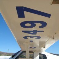
Bruce Tuncks Posted September 2, 2018 Author Share Posted September 2, 2018 Here it is Ken. I reckon it is easier to keep the skid ball in the center. And I reckon it looks better. It passed a proof-load test before flying. Because the old leading edge is still in there, it has effectively got 2 spars, that is the rudder-spar plus the old leading edge which has now become a spar. I have been trying to measure if there is any loss of rudder effectiveness. The max sideslip angle would be less I think if there was a loss here. I can't see any difference. Today I did a take-off with near maximum cross wind and again I couldn't see any difference. Link to comment Share on other sites More sharing options...
Recommended Posts
Create an account or sign in to comment
You need to be a member in order to leave a comment
Create an account
Sign up for a new account in our community. It's easy!
Register a new accountSign in
Already have an account? Sign in here.
Sign In Now