Ross
-
Posts
729 -
Joined
-
Last visited
Content Type
Profiles
Forums
Gallery
Downloads
Blogs
Events
Store
Aircraft
Resources
Tutorials
Articles
Classifieds
Movies
Books
Community Map
Quizzes
Videos Directory
Everything posted by Ross
-
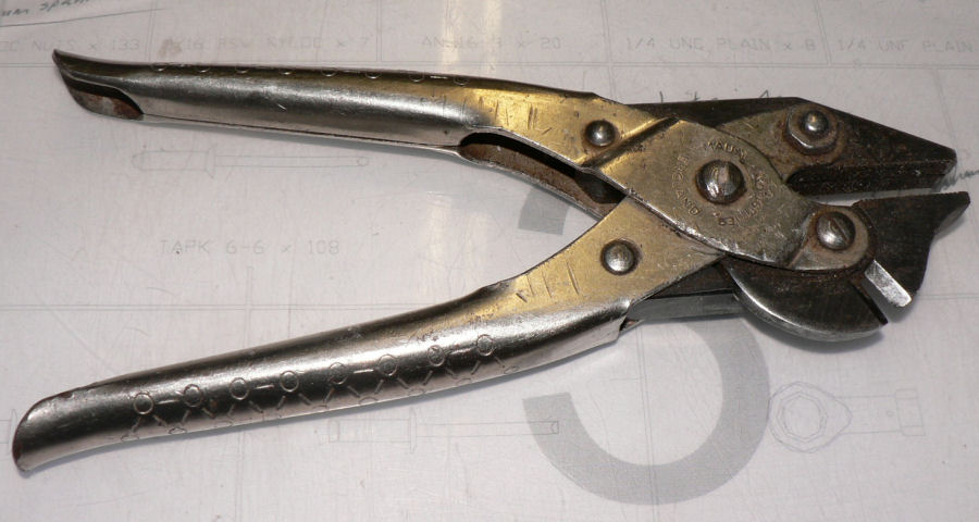
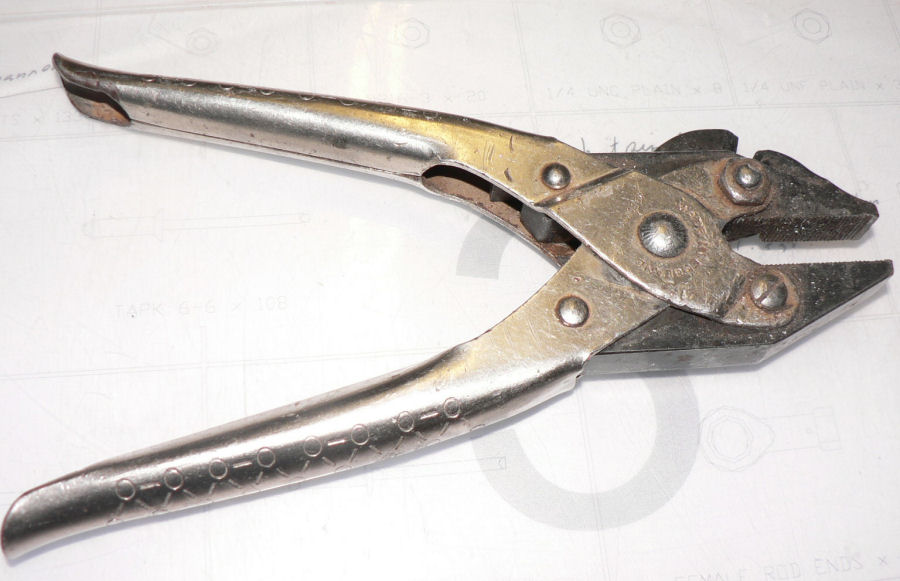
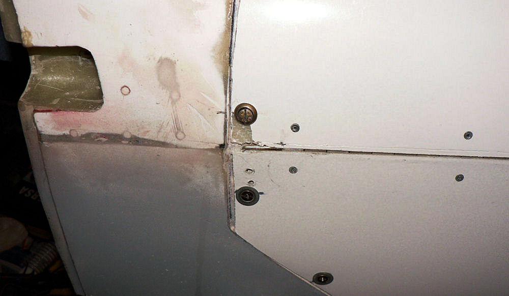
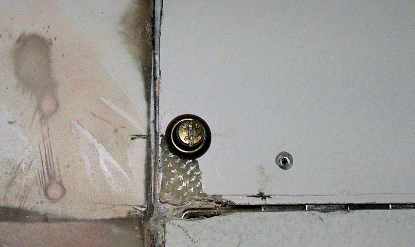
Another way out of the problem might be to put a little dab of opoxy mixed with flock in the second hole of each location where a self tapping type screw is used and then insert the self tapper. If you are unable to extract them later with a Philips head screwdriver I find that a pair of Fencing pliars specifically designed to handle high tensile wire will allow you to grip them hard enough to rotate them for extraction. [ATTACH]4564.vB[/ATTACH][ATTACH]4565.vB[/ATTACH] The jaws in these pliars are hardened steel and unlike most pliars stay parallel as they are opened or closed. They will also cut spring steel without damage to the cutting edge. Regards

-
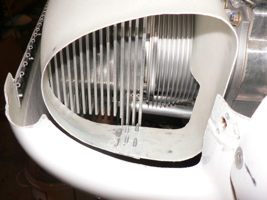
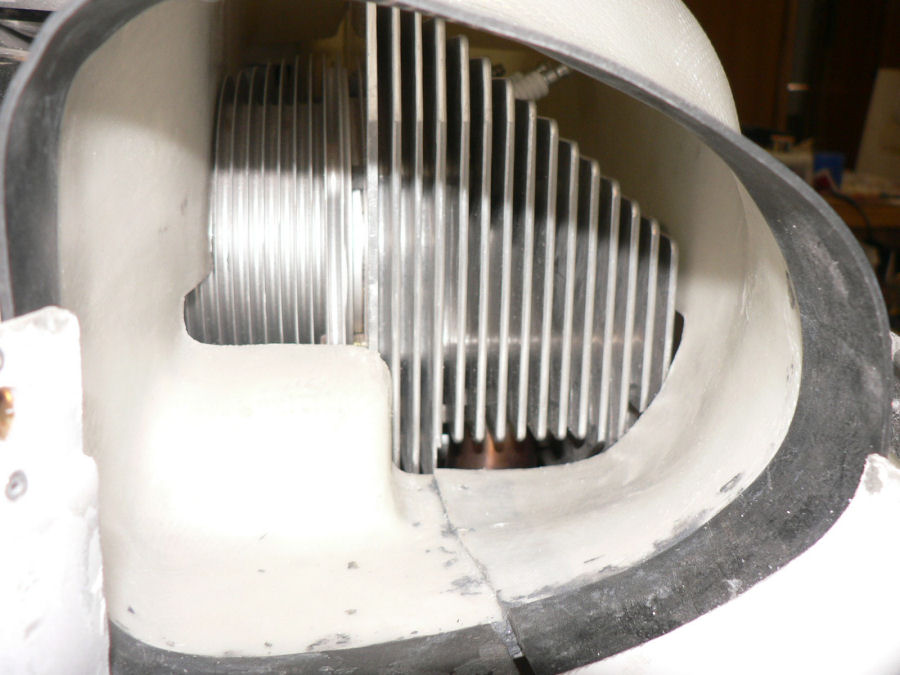
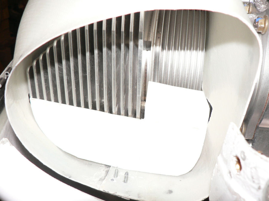
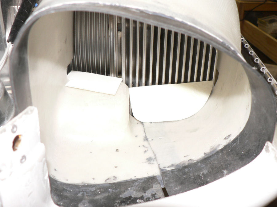
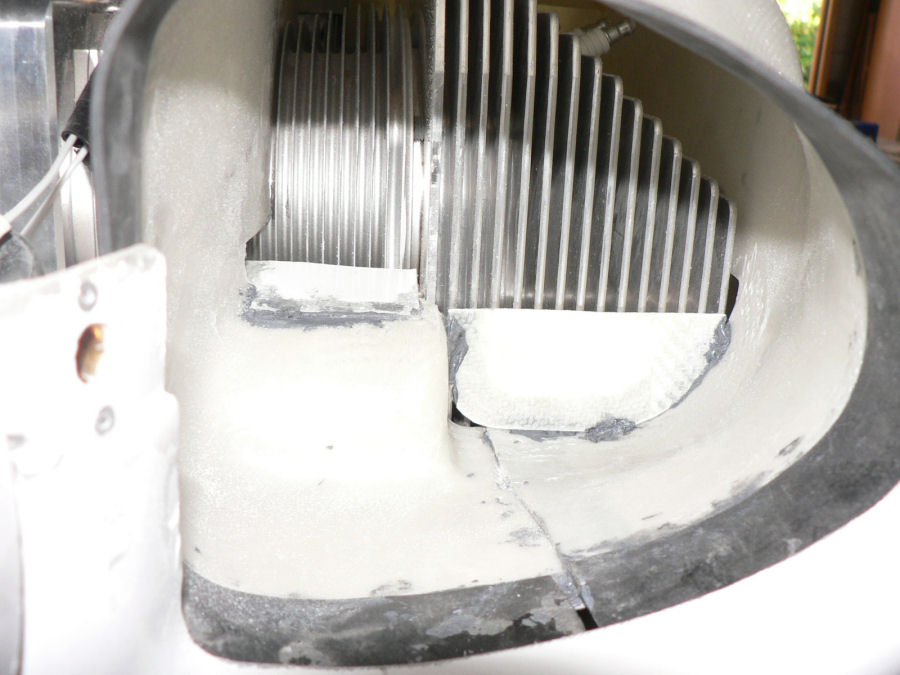
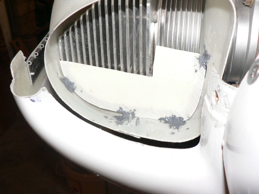
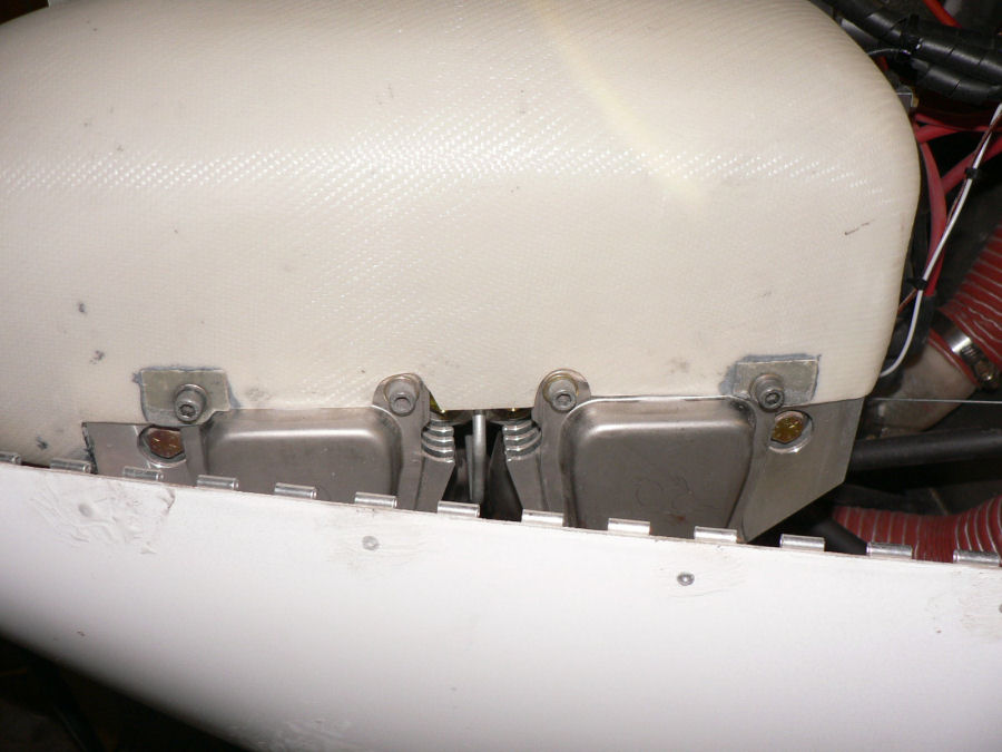
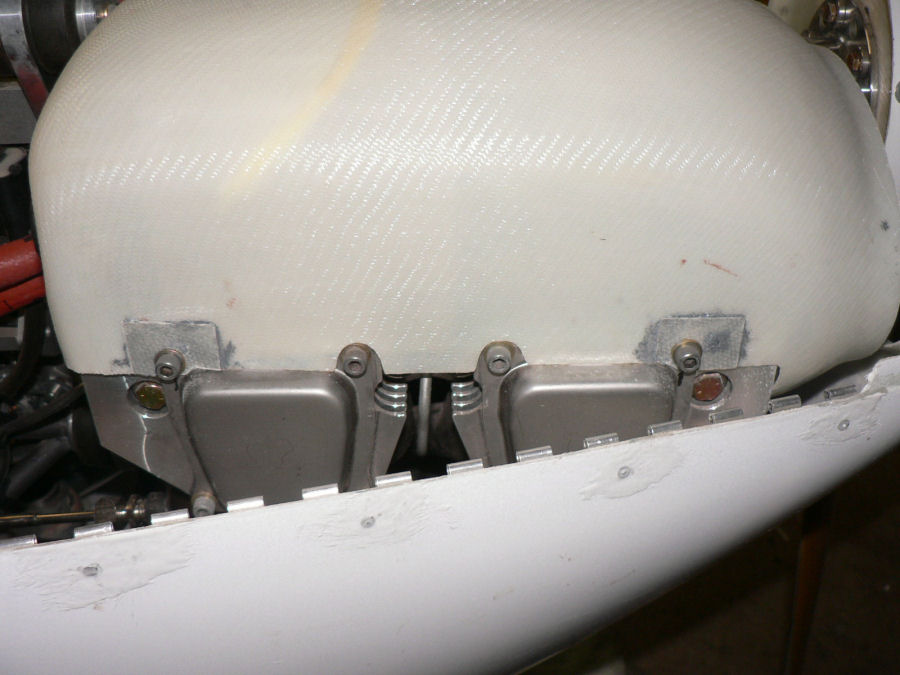
15-16-12-2007 Used Loctite Quick Adhesive (a "10 minute epoxy") to tack the LH Ram air cooling duct opening hole size. The epoxy is a horrible grey colour and sets very quickly and is very hard to get out of the tube - old stock? - although it seems to work very well. It is the same price as 5 minute Araldite in Leeton. It is easy to mix as the hardener is pure white and the resin is black so when mixed is a uniform grey colour. Improved mounting hole alignment of cooling ducts to the tappet covers for both LH & RH ducts sides and reinforced the hole positions with an extra layer of fibreglass attached with loctite adhesive. Every Jabiru I have seen with the top cowl off shows wear in these duct mounting holes. Pre fitted LH cooling duct & trimmed it to give about a 12 mm or 1/2" gap between the duct and the edge of the cowl air entry hole. This will allow the insertion rubber to be pushed out over the lip once it is fitted. Fitted insertion rubber supplied to LH cooling duct. Roughed up the insertion rubber and the matching part of the duct with emery cloth. Cleaned both surfaces with acetone. Applied quick setting Loctite adhesive to both surfaces and clamped rubber using multiple spring clamps. Adjusted opening of RH cooling duct to more closely match the cowl openings. Set the opening using epoxy adhesive again. AS above adjusted the gap between cowl lip and duct to about 12 mm. Checked the air gap inside the ducts between the duct and the first cylinders on each side. The gaps on both sides would let a lot of air escape without cooling the cylinders. So made up pieces to tack inside the ducts using the quick set epoxy - they will be flocked in later more securely. These pieces should force most of the air to go over the top of the cylinders and come down between them and over the end ones. [ATTACH]4556.vB[/ATTACH][ATTACH]4557.vB[/ATTACH][ATTACH]4558.vB[/ATTACH][ATTACH]4559.vB[/ATTACH][ATTACH]4561.vB[/ATTACH][ATTACH]4560.vB[/ATTACH][ATTACH]4562.vB[/ATTACH][ATTACH]4563.vB[/ATTACH]
-
The 296 also has 12V 24V cigar power supply that automatically charges the battery if it is low as well as running the GPS. If the external aircraft 12V fails the internal GPS battery takes over depending on what options you set up. Regards
-
Hi Alan I note that your "nuts" that are used between fairings look like the push on type that were commonly used on some car panels years ago together with self tappers. I ordered an extra supply of retained nuts from Jabiru (the type that require two rivets to secure them) and are mated with a machined SS screw either CSK, Pan head or hexagon head as required. My bottom cowl uses CSK stainless screws with the retained nuts. The instrument panel uses on my #14 J160 kit pan head screws with retained nuts. The locking tabs for all the control hinges use pan head screws with the retained nut (held by two pop rivets). I have used them to secure items like fairings to fairings around the UC legs and struts & the strut fairing to fairing on the wing connection and the extension to the centre console between the pilot & passenger. I still used the self tappers to connect removable fairings to the fuselage. There is far less chance of these screws with retained nuts falling out, getting loose or the hole enlarging when compared to using the self tapping screws. Regards
-
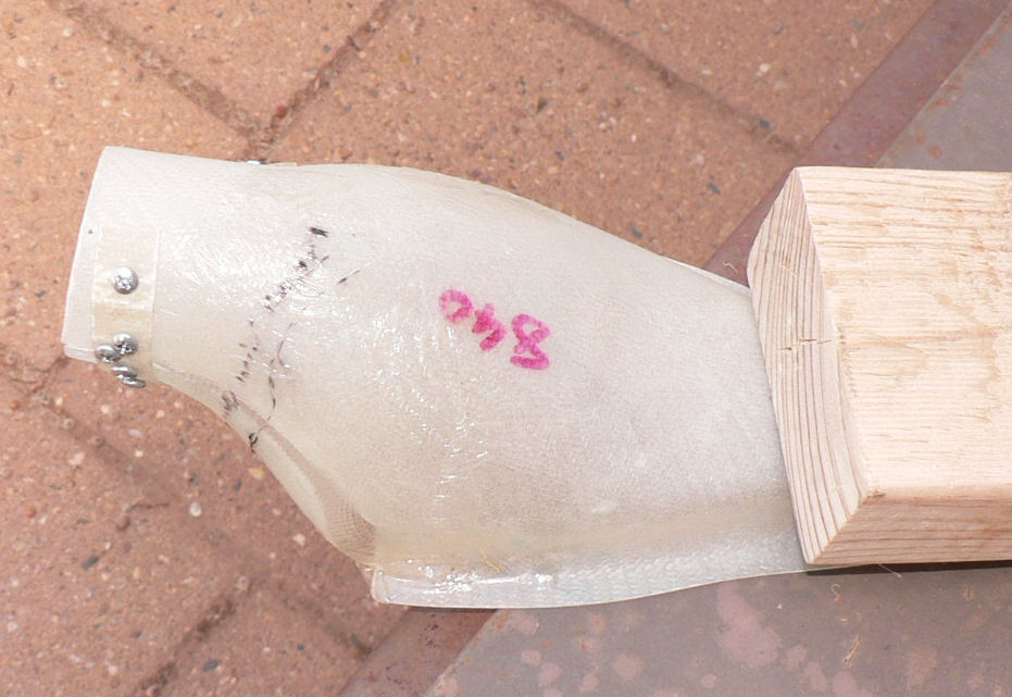
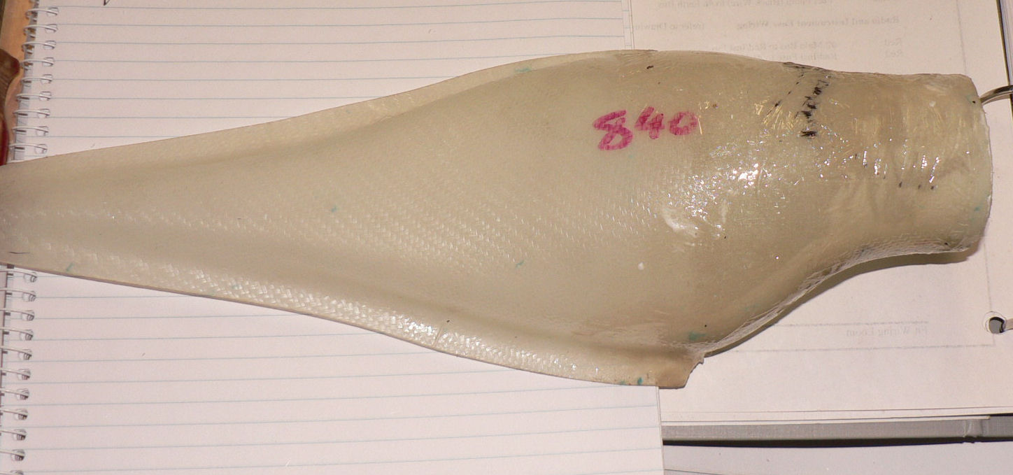
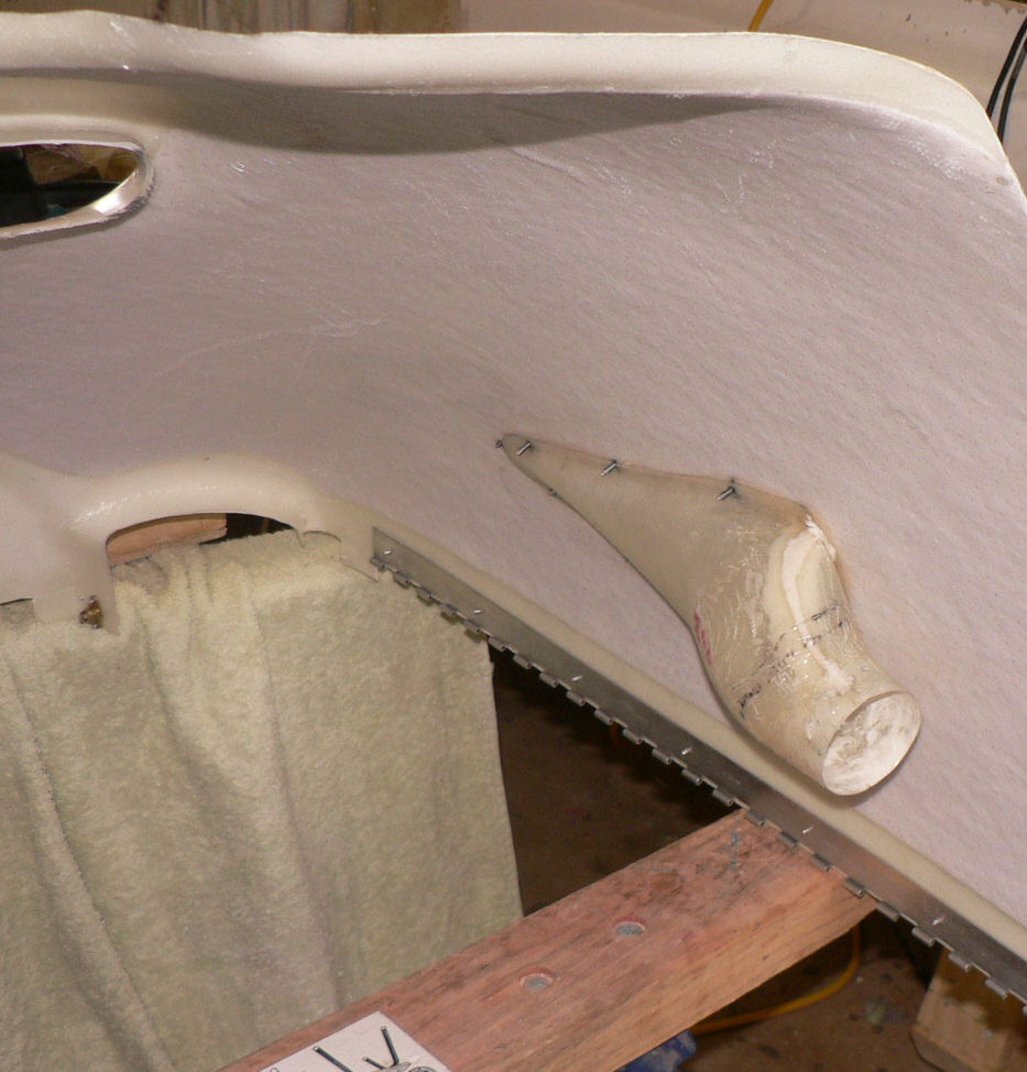
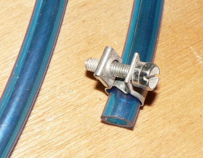
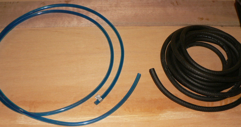
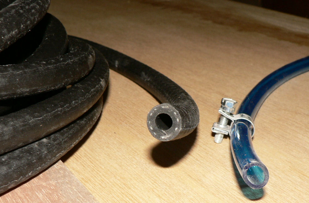
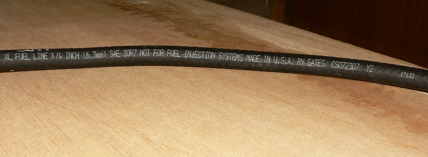
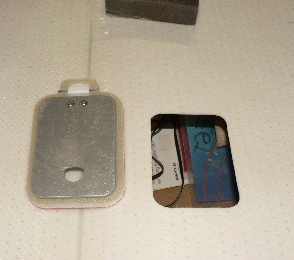
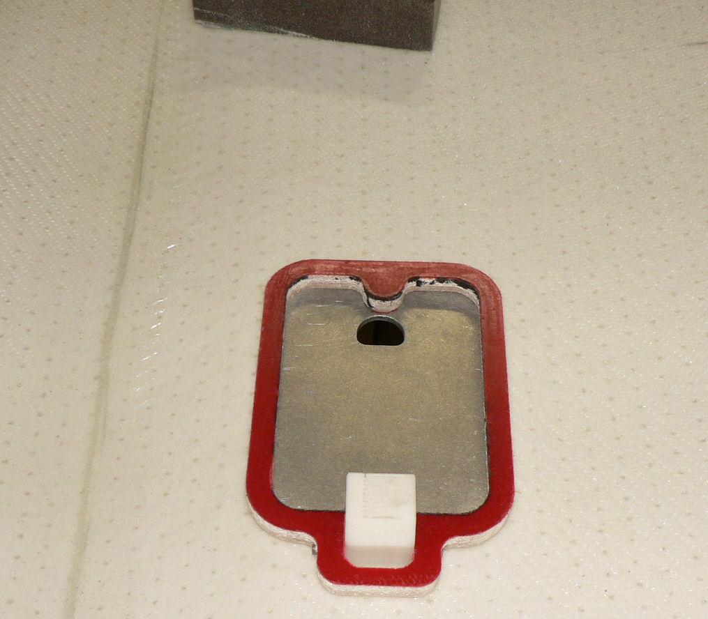
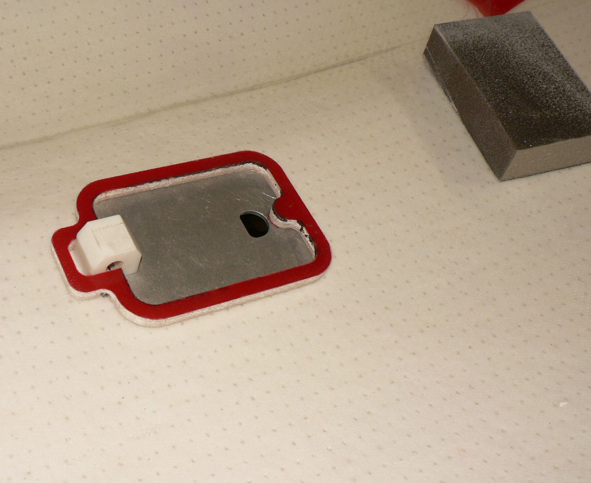
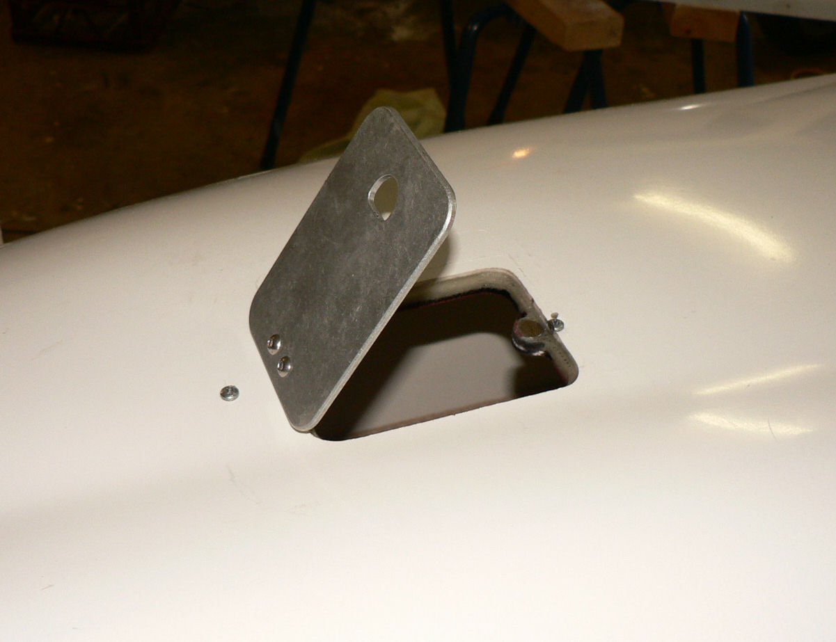
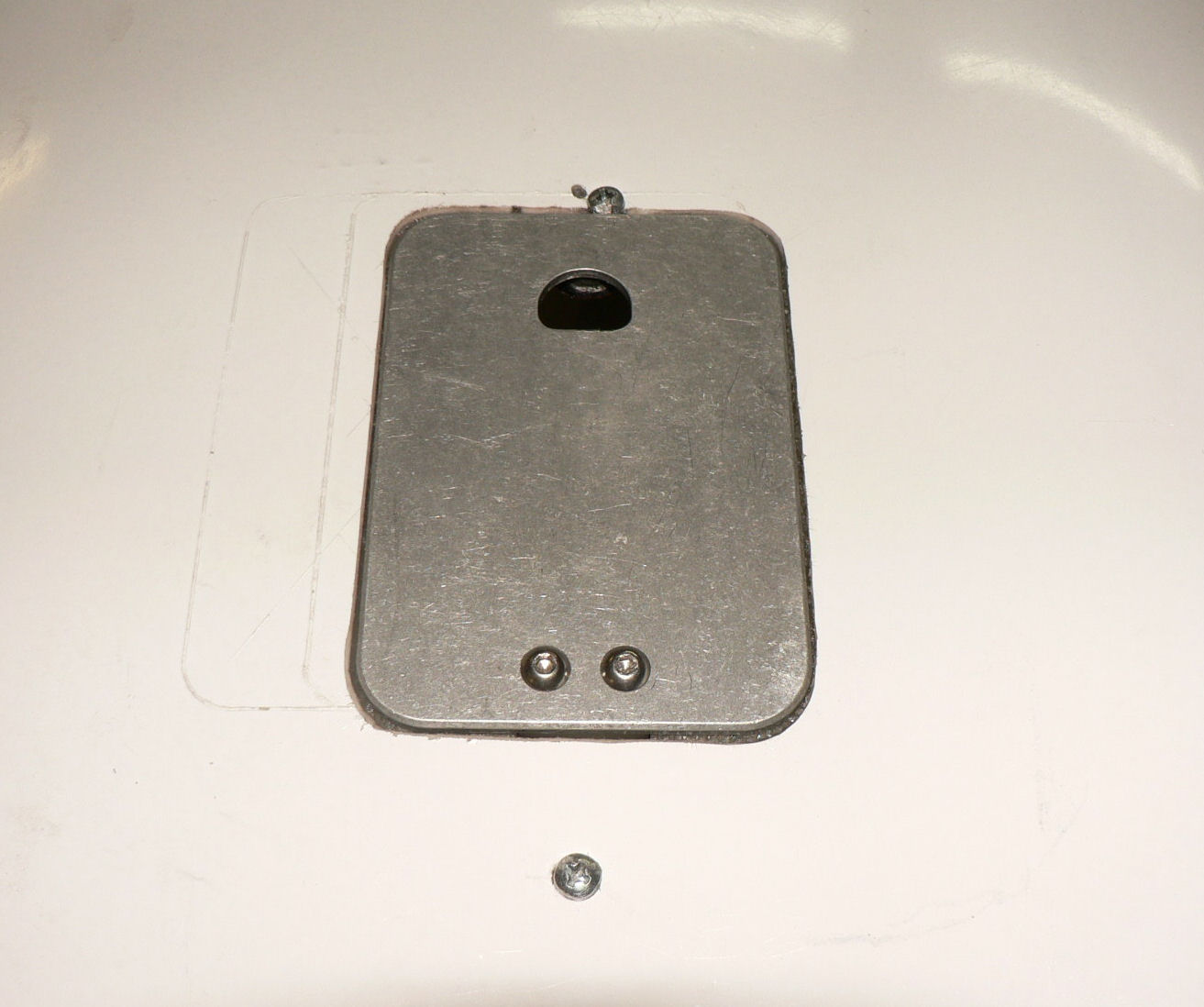
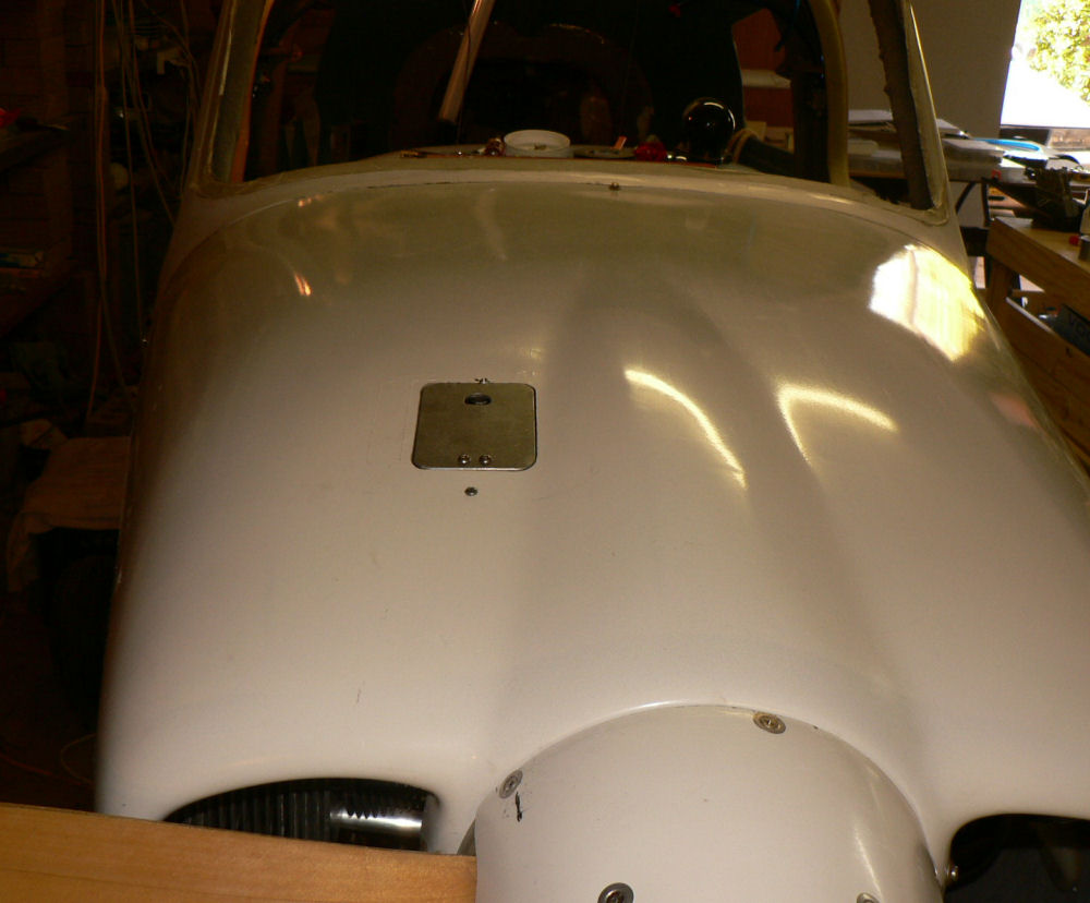
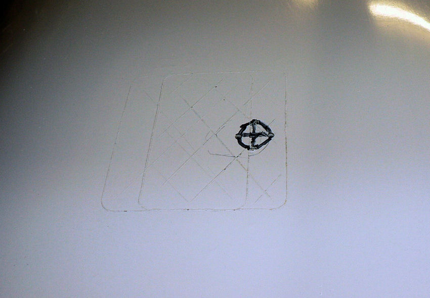
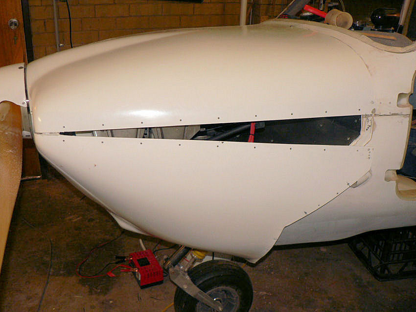
11-12-13-14-12-2007 Installed a 3.5mm socket on the instrument panel for "mono music" input to the PM501 intercom. I might also put in a 2.5 mm socket as well. It works and goes into background mode for the passenger and pilot for any inbound radio calls. If the Intercom is put on "isolate" the pilot does not hear the music at all. Jabiru parcel arrived on 14th with "induction" hose clamp, 2.25" scat hose, black fuel hose to replace the kit supplied blue plastic line. [ATTACH]4537.vB[/ATTACH][ATTACH]4538.vB[/ATTACH][ATTACH]4539.vB[/ATTACH][ATTACH]4540.vB[/ATTACH] No hose clamps were supplied with the new black fuel hose. It needs about 25 clamps. The original clamps supplied with the original blue plastic (fuel hose?) made me very nervous as they were never tight on the fittings and are too small for the newly supplied black fuel hose. Paul at Jabiru said just buy ordinary hose clamps! My guess is about $50 for 25 clamps. So filled some more temporary screw holes with epoxied micro-ball filler. Put the NACA duct together using fibreglass cloth wrapped around the assembly and clamped in place with screws and pieces of scrap fibreglass . [ATTACH]4533.vB[/ATTACH][ATTACH]4534.vB[/ATTACH][ATTACH]4535.vB[/ATTACH][ATTACH]4536.vB[/ATTACH] Prefitted NACA air inlet on bottom cowl & then flock it to the cowl. Cut the new scat hose ($77.50/metre) from air cleaner mixer to NACA duct mounted on the bottom cowl. Cut out the access hole in the top cowl for the oil dipstick & filler cap. The new lid for the inspection hole has a magnet to secure it in the closed position against a steel washer super glued to the hinged aluminium lid. [ATTACH]4541.vB[/ATTACH][ATTACH]4542.vB[/ATTACH][ATTACH]4543.vB[/ATTACH][ATTACH]4544.vB[/ATTACH][ATTACH]4545.vB[/ATTACH][ATTACH]4546.vB[/ATTACH][ATTACH]4547.vB[/ATTACH] Flocked the seat for the lid to the cowl after roughing up with an emery block, cleaning with acetone, priming with epoxy. [ATTACH]4548.vB[/ATTACH] The sun in this shot this evening at 20:02 hrs eastern Australia summer time was blood red - Panasonic DMC-FZ5 digital camera does not do it justice. Cannot fly at Narrandera this weekend as the airfield is closed for resurfacing for two days.
-
Looks like a very flyer friendly place when you count the number of headlands that the cropping person had to do compared to the non aerodrome paddocks beside it.
-
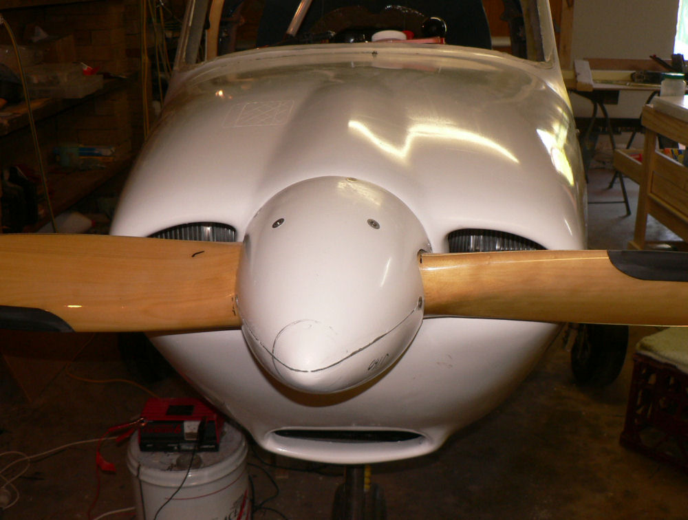
10-12-2007 Peter I might even get to Narromine myself in 2008. The last time was 2004. It will probably depend on if Easter is Early or late in 2008. Just checked Good Friday is 21st March. Might be pushing it if anything goes wrong and there are delays. Plus I already have a niece's wedding to attend in Melbourne. Waiting on inlet manifold hose clamp and scat hose from Bundaberg. Attached the cowls with most of the bottom screws inserted but not all. The position of the oil filler and dipstick was marked on the top cowl. [ATTACH]4510.vB[/ATTACH][ATTACH]4511.vB[/ATTACH][ATTACH]4512.vB[/ATTACH][ATTACH]4513.vB[/ATTACH] The factory marked out position for the cover would be better moved over a bit.
-
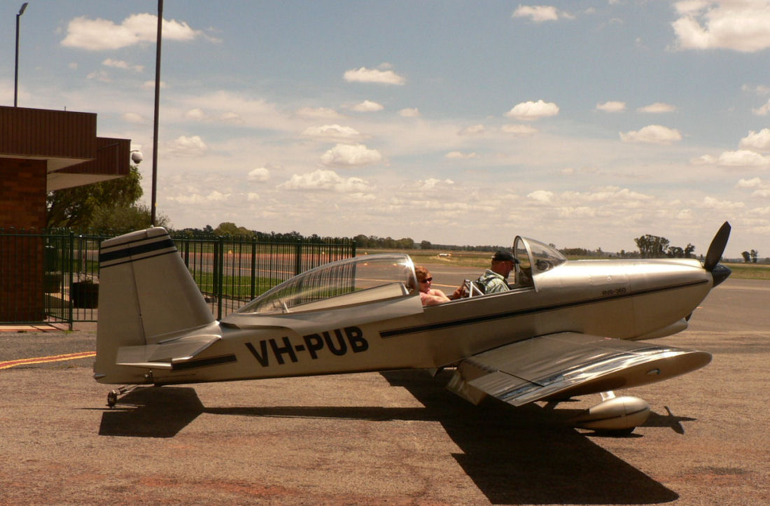
Hi Peter Yes I can see a distant light that I hope is the end of the tunnel! I am doing odd bits at the moment. Jamie at Jabiru just rang to verify a scat hose order I made by e-mail on Saturday night - I thought it measured 2 3/16". He said they have 21/4". I said OK. Thanks for the weight info. What did the front UC wheel go empty? By the way this J160 only has dual controls as no commitment has been made to actually get in the right hand seat. I hope to convert to duel eventually. But I think my other half is a bit like John Herrmann's wife who is so interested in flying that she is known to read a book while flying with him in their RV8-360. See pic below. [ATTACH]4508.vB[/ATTACH] Caught them at Narrandera flying back from Corryong 20071202 12:48. Regards
-
Looking at the newest J230C at Narrandera recently and noticed that its Jabiru wooden propeller appears to have a leading edge insert quite different from the props on the other two J230Cs in the hanger. Does anyone know any more about this insert?
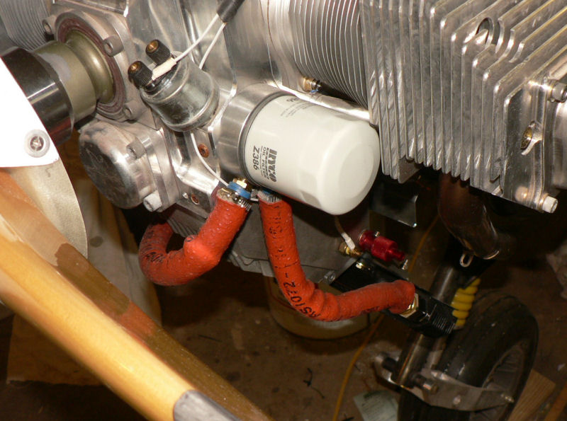
-
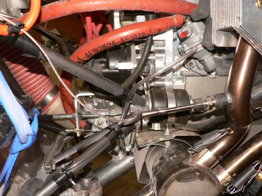
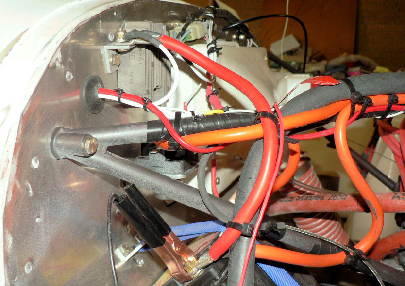
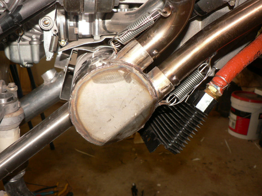
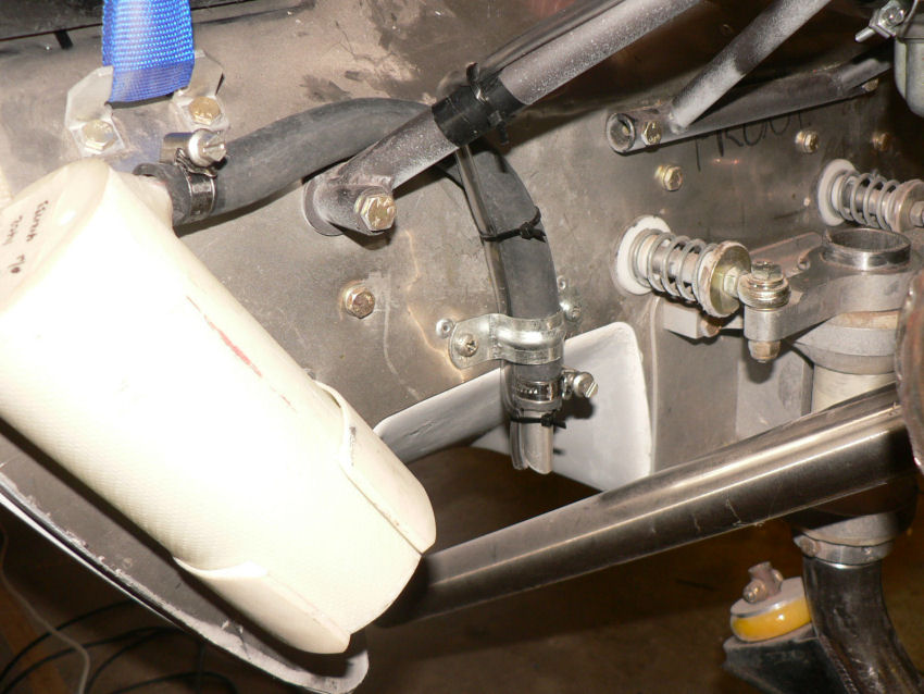
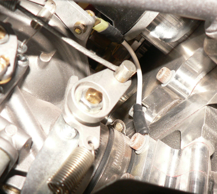
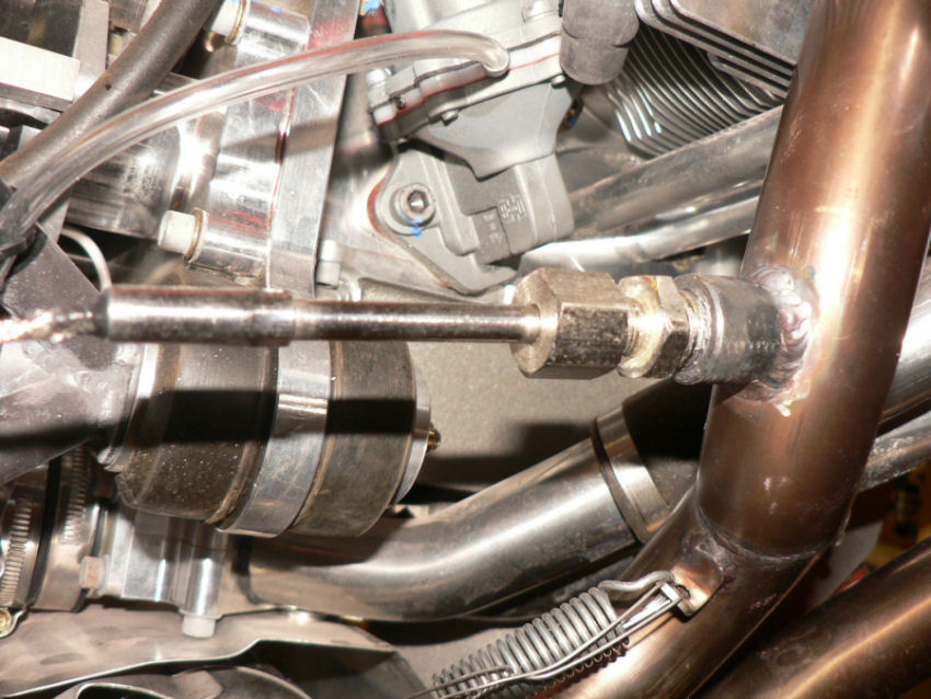
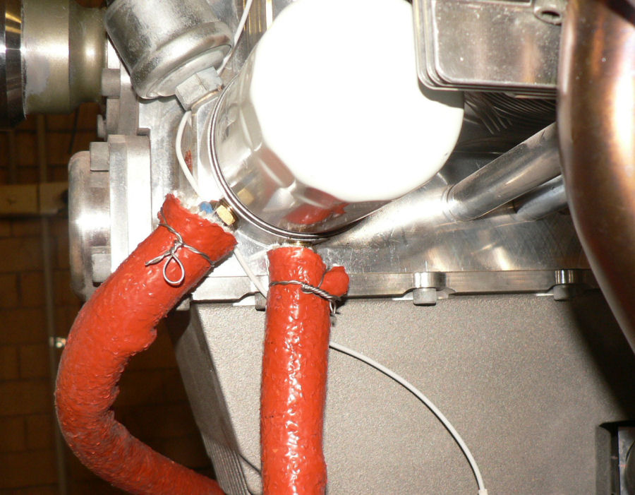
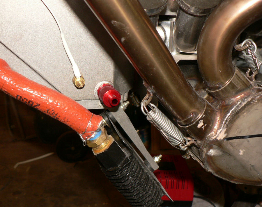
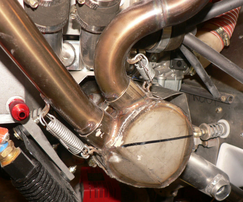
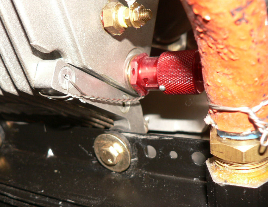
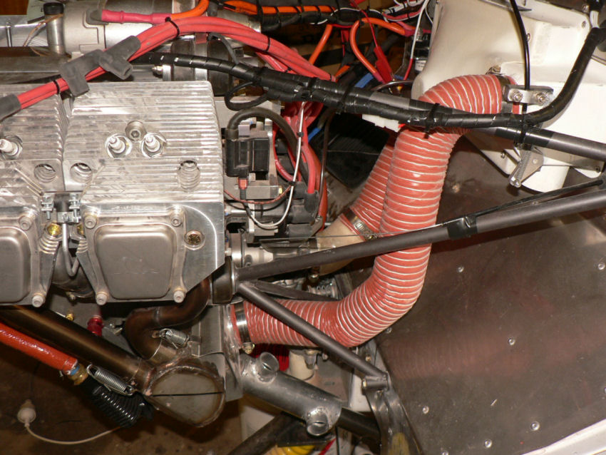
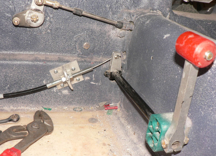
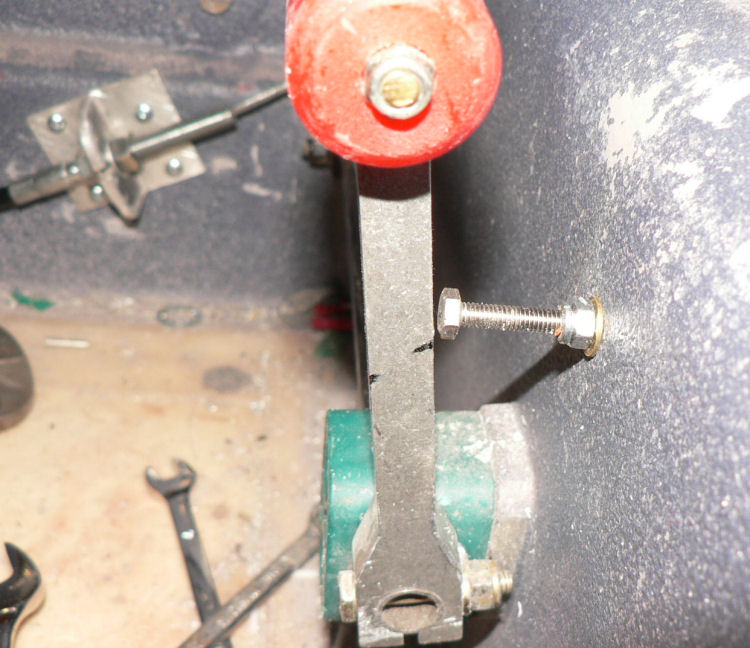
8-12-2007 We had a blackout in Leeton this morning till about 6:15 am so my welder had not started when I turned up at 7 am at his workshop. By 8 am was able to pick up the newly welded exhaust pipe with SS boss for EGT probe. No mention of Titanium! My garage man was loading the other car on his trailer when I got back home! He got too busy the previous day. Jobs done during the day. Test the EGT with hot air blower. It went to about 230 degrees C, check the pic it had dropped as I removed the heat source. [ATTACH]4501.vB[/ATTACH][ATTACH]4502.vB[/ATTACH][ATTACH]4503.vB[/ATTACH] Installed the #3 exhaust pipe with sensor boss fitted. Installed the EGT sensor in the exhaust pipe. [ATTACH]4496.vB[/ATTACH][ATTACH]4491.vB[/ATTACH][ATTACH]4492.vB[/ATTACH] Fitted the muffler and attached the retaining springs. [ATTACH]4493.vB[/ATTACH] Modified wiring to suit alternator red LED warning light. I think it is OK now. Red LED showing here for low voltage plus Green LED for powered up Main bus (appears almost white in pic). [ATTACH]4505.vB[/ATTACH] The light 16 gauge positive wire of output alternator from from the regulator goes to the main bus (which is not activated until the key is turned on ). The other alternator 10 gauge heavier wire from the regulator goes straight to the battery positive. Note the factory fitted carburettor earth wire to help reduce radio interference. [ATTACH]4494.vB[/ATTACH][ATTACH]4495.vB[/ATTACH] Did more cable ties in the engine compartment & behind the panel. Did lock wiring on oil cooler hoses & oil adapter hose connections. [ATTACH]4497.vB[/ATTACH][ATTACH]4500.vB[/ATTACH] Lock wired the muffler retainer springs. [ATTACH]4498.vB[/ATTACH][ATTACH]4499.vB[/ATTACH] Installed the scat hose from air cleaner to carburettor. Installed the carburettor heat scat hose from muffler heat muff to air cleaner. [ATTACH]4504.vB[/ATTACH] Ran out of scat hose for the connection to the cowl engine air. Connected the throttle cable to carburettor & set the stops approximately. Fitted a low throttle stop. Still need to flock in a maximum throttle stop in the cabin floor under the throttle lever. [ATTACH]4506.vB[/ATTACH][ATTACH]4507.vB[/ATTACH] Note if throttle cable disconnects from carburettor, the throttle goes to wide open - maximum setting! Connected the choke cable & set the stops.
-
6-12-2007 Hi Brent thanks for that. My aim was for zero toe in but my confidence in my measurements is quite low because of the irregularity of the wheels. I did expect it to sink as it has not even got its wings on at the moment let alone 135 litres of fuel, 2 POB and other odds & ends. We went to Wagga today 270 km round trip for my first annual check up after the cataract operation earlier in the year. All OK so far. He put drops in my eyes to open up the pupils which made it quite uncomfortable trying to see in bright sunshine and bright lights in some of the shops until the drops started to wear off. I could not have driven home without a good pair of sunglasses - into the setting sun as usual. I got a new set of wheels and a couple of axles at Bunnings. I already have some plywood and maybe enough bolts to build a billy cart for the two grandchildren boys, 3 yo & 5 yo, when they visit over Christmas. I hope the build doesn't eat into J160 time too much. I have delegated the decoration to "she who must be obeyed". I must tell her at a suitable moment! The boys are allowed to sit in the J160 but their father told me they were not allowed to fly in it. Maybe I should put wings on the billy cart. I also discovered a digital set of scales at Bunnings for $19-90c so bought two of them. I shall have to calibrate them as well. Three plastic jerry cans full of water would give me about 150 lbs or 68.2 Kg plus another 2 Kg or so for a piece of wood to sit them on. Does anyone know the approximate weight on each wheel for a fully rigged J160 with and without fuel? After we returned from Wagga, rang Jabiru re the exhaust pipe & EGT probe boss and was assured by Rod that both were made from SSteel. Also through Paul ordered some more wire 10# and 16# plus some spare inlet manifold hose clamps. Today I saw some Ryco Z386 oil filters in Wagga Kmart at a bit under $16 each (as supplied on the Jabiru 2200 motor). So I bought a couple of them. Let's hope I get to need them. Yesterday was not a good day for me. I had taken our second car down to get its air conditioner recharged to be told it was stuffed and needed a new compressor - $810 so then ordered it and drove the car home. However on the way home it was obvious there was a major problem in the front end appearing as though the RH front wheel bearing is about to seize solid. So tomorrow my garage man is coming to pick it up and fix it. My auto electrician told me the new compressor arrived today when I checked with him. I told him he was now second in line. Rang the welder to tell him about the SS & SS. So he will probably weld the boss onto the exhaust pipe tomorrow afternoon. I am getting confused, so changed my signature to Ross A. I note that it has changed on previous posts as well.
-
Welcome to the site Phil. We stopped (driving) overnight with friends at Uralla on the way to the Gold Coast back in December. I spent some time telling them about the advantages of RAA flying. They already knew I had/am been assembling a J160 kit forever (almost three years now) and was also involved in gliding for many years at Leeton. Coming from Leeton (on the edge of fairly flat country), I reckon that anyone who lives at Uralla would really appreciate being able to fly when they want to go somewhere that is more than about a 50 km drive. Where are you going to eventually operate your AC from. Regards and enjoy your new skill.
-
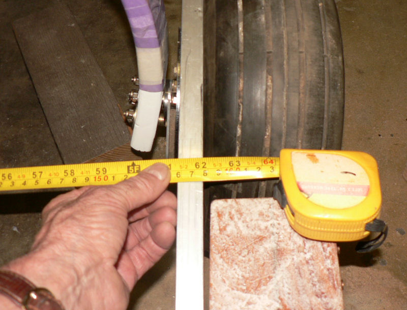
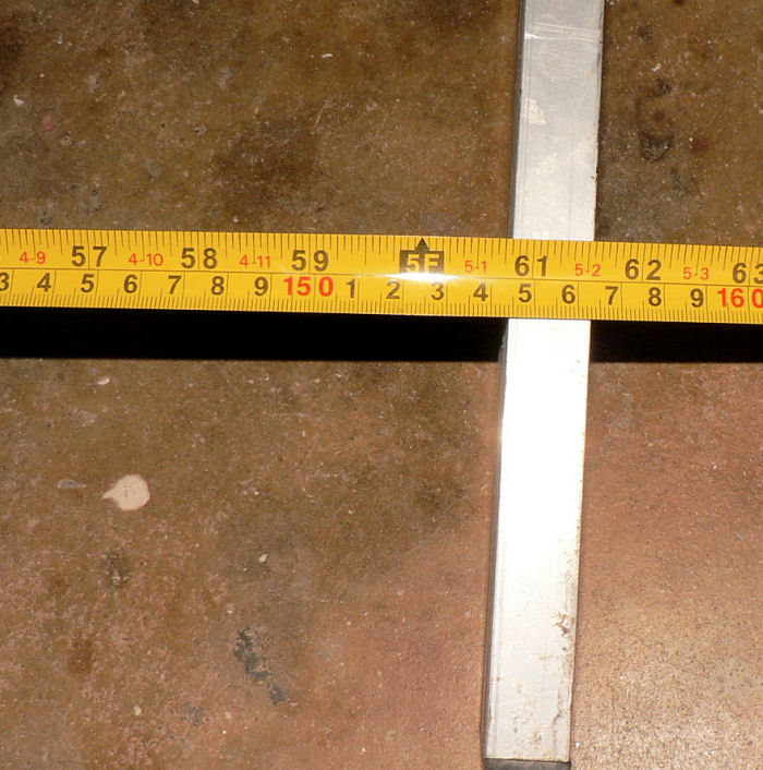
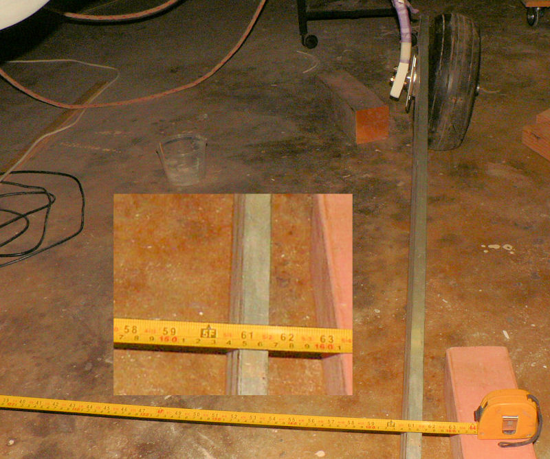
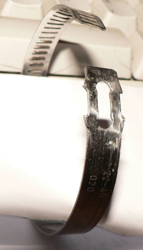
5-12-2007 Welder claimed the exhaust pipe was made of Titanium and the exhaust gas temp sensor mounting boss, 1/4" NPTF 18 tpi thick wall pipe socket like, is in SS which are not really compatible for welding. Will check with Jabiru. Longer bolts for the stub axle mounts arrived in mail this morning - they were waiting on their suppliers for 1 bolt before dispatching the order on Monday. Packed up both axles to stand straighter and reduced the toe in as measured at the front wheel across the straight edges. When I finished, with two straight edges sitting between a brake disk and its corresponding tyre they measured 1575 mm at the leading edge of the main wheels. In the pic the tape is a bit loose - should have used the tripod. [ATTACH]4457.vB[/ATTACH][ATTACH]4459.vB[/ATTACH][ATTACH]4458.vB[/ATTACH] They were about 1563 mm total at a point measured to the middle of the front UC wheel with both sides very close to being equal. The cast aluminium rims do not help the process as the wheels are obviously not true when spun freely. When I finished it was far easier to push the plane around but the tyres still squeal on the smooth concrete in the carport so they are not yet set to zero toe in. One washer difference between the stub axle base front and rear on each main wheel was enough to change the total toe-in measured at the front UC wheel by about 100 mm. If I persist with this exercise I think I shall have to get some brass shim material of various thicknesses so that I can make finer adjustments to the toe-in. In another life and another time and place at The Australian Iron & Steel Co at the Port Kembla works, we used brass shim in sheets it in similar applications for packing and lining up bearing blocks in line shafts etc. While one of the exhaust pipes is off it was an opportunity to tighten the hose clamps on the inlet manifold pipes (and the clamp screws on the remaining exhaust pipes). These hose clamps must have been fitted and tightened before the exhaust pipes were fitted. As a result some clamps could not be checked or tightened so I loosened the offenders off and rotated the clamps to make them accessible with the exhaust pipes fitted and tightened them again. During this process I managed to get one clamp that gave up on me and on inspection it appears to have a manufacturing fault. [ATTACH]4460.vB[/ATTACH] There appeared to be a slight miss-match between the clamp locating the worm drive and the length of the left hand recess in the edge of the clamp band resulting in failure when tightened. Another delay.
-
4-12-2007 Removed the cowls. Secured the oil breather overflow hose and the fuel pump drain with a clamp & cable ties. Fitted scat hose & fitting from carburettor to air cleaner. Rearranged engine earth cable routing & cable ties in engine bay. Added a couple of saddles to carry wiring across the firewall. Removed #3 exhaust pipe for welding of EGT fitting to hold EGT sensor. Tried the extra terminal on the oil pressure sensor as a sender for low pressure warning light. As Jabiru say in the manual - not used. Noticed the carburettor needs to be earthed to the engine to help reduce any possible radio interference. Not done yet. Removed spark plugs and checked the gap. All within spec. Replaced with anti seize on thread. [ATTACH]4434.vB[/ATTACH][ATTACH]4435.vB[/ATTACH][ATTACH]4436.vB[/ATTACH][ATTACH]4437.vB[/ATTACH][ATTACH]4438.vB[/ATTACH][ATTACH]4439.vB[/ATTACH] Still waiting on parts ordered from Melbourne by a firm using paymate on 28th Nov. They have already advised me by email twice that funds were debited against my mastercard account on 28th Nov. I have checked my MC account to see that it was debited on 28th Nov. Noticed on a Jabiru230C at Narrandera a bit over a weeks ago that their wheel axles have a spacer washer fitted on the axle effectively moving the wheel out by the thickness of the spacer washer further away from the brake pad if their axles are the same as my J160 axles. My unused brake pads just drag lightly on the the metal disk without the outer half being fitted yet. It would also give slightly more clearance for some of the bolt heads in the assembly.
-
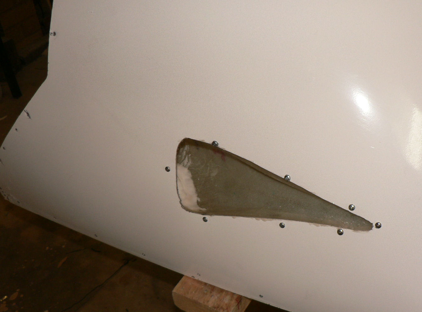
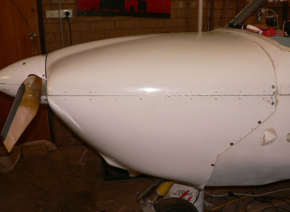
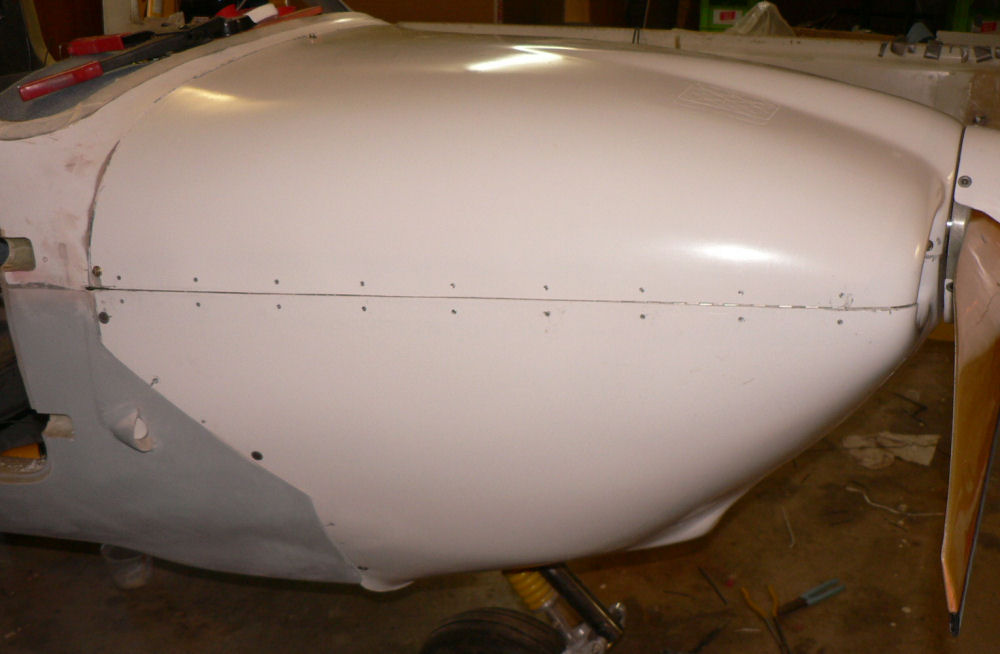
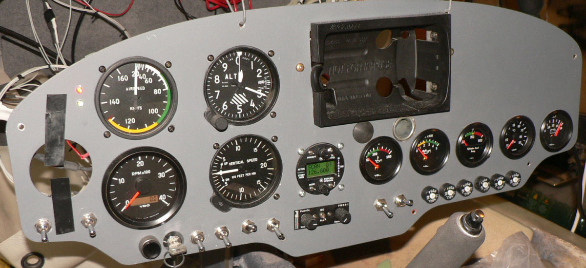
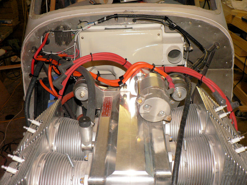
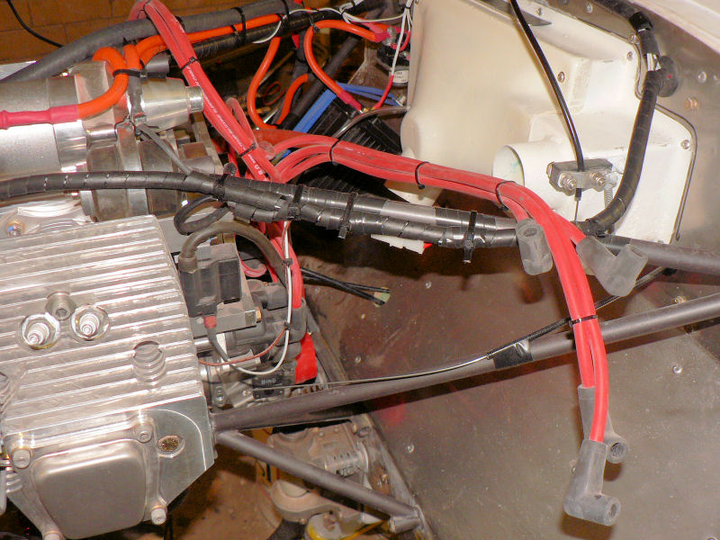
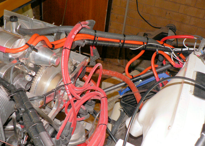
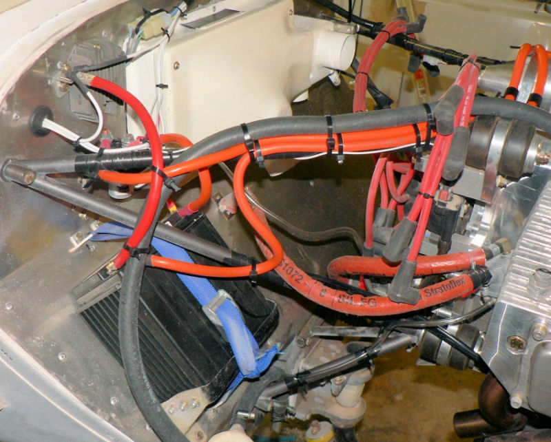
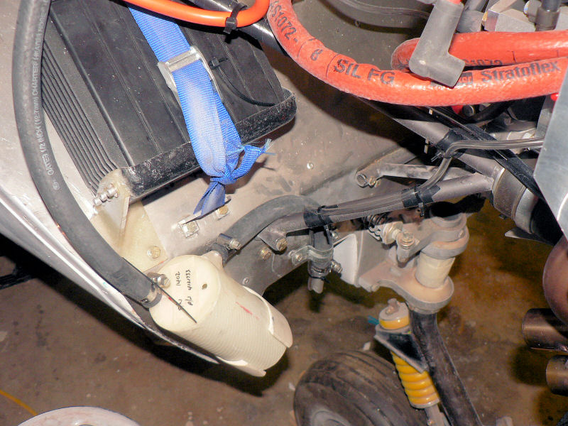
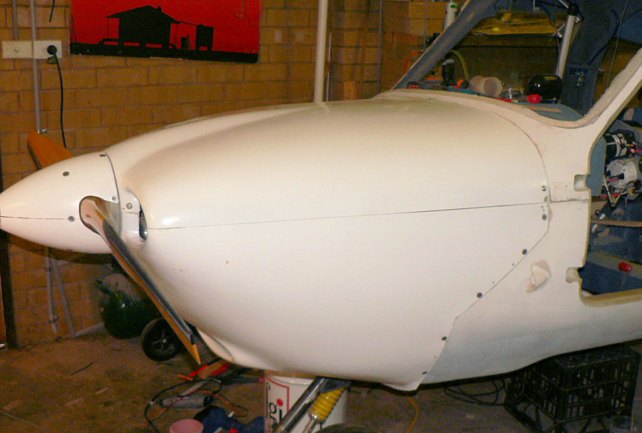
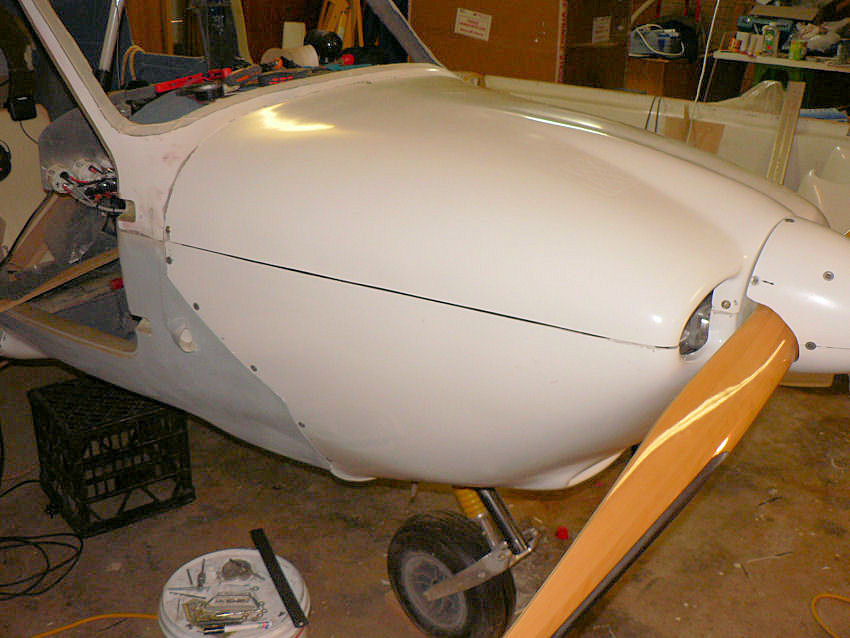
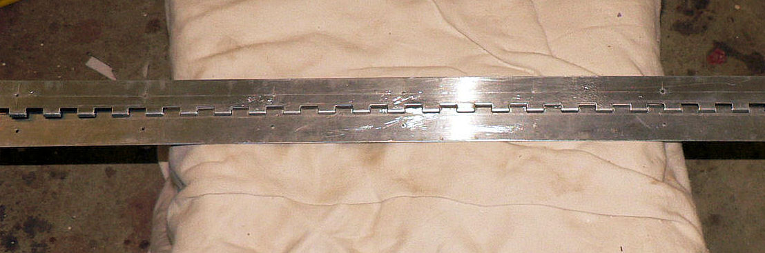
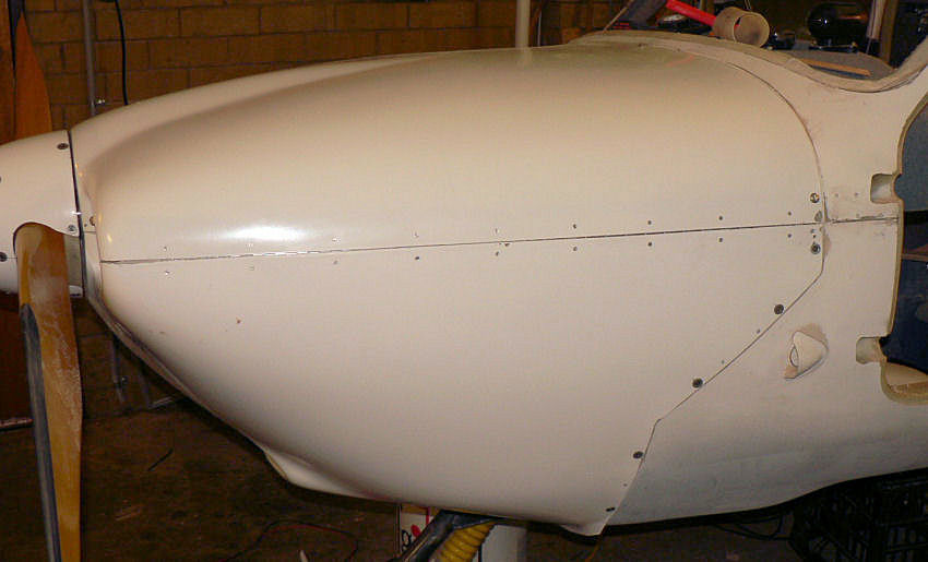
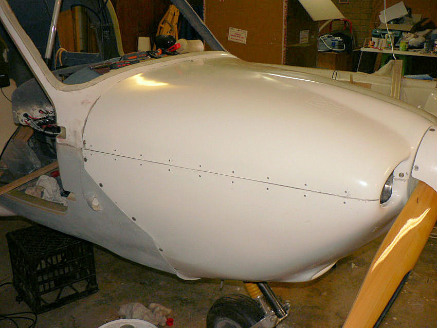
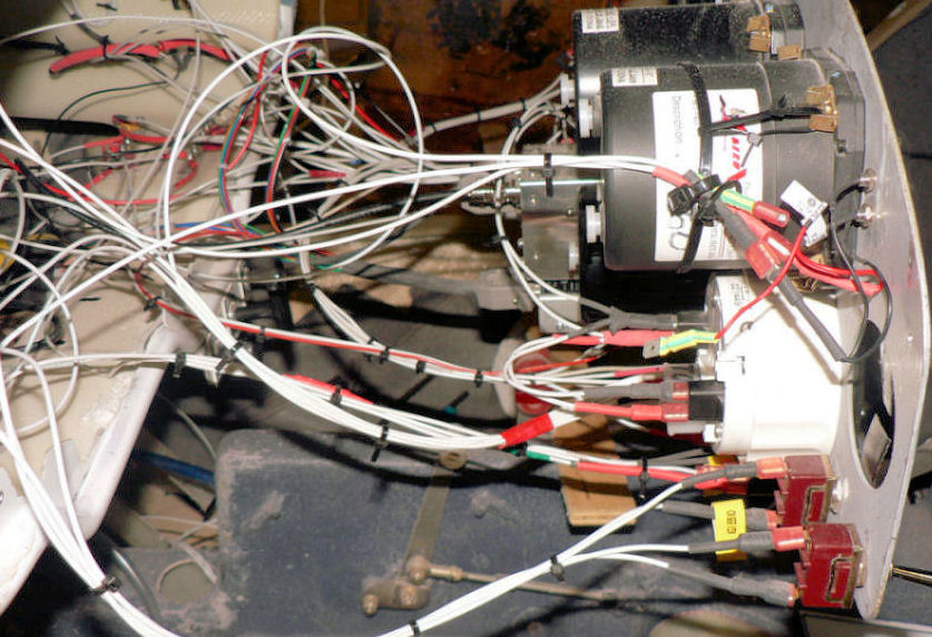
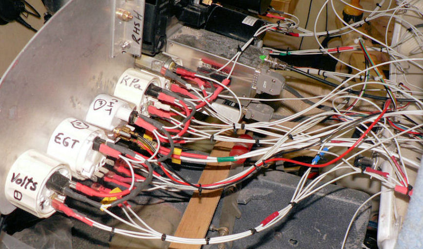
28-11 to 03-12-200 Decided to install new style cowls top & bottom for J160 as my has a long oil cooler mounted across the sump. The new style cowl already has a lip on the bottom to improve air flow but still needed the oil cooling air intake to have a few cms removed from the inside edge to avoid fouling the oil cooler and to match the angle of the oil cooler. The aluminium piano hinges for the cowls were marked very carefully along their length with a carpenters marking tool - don't know the name- then at 95 mm centres using a steel compass they were marked off and then centre punched for drilling both sides of each hinge together with the hinge pin installed. This made it possible to use either half of the hinge as a template when marking and drilling the cowls for the rivets to hold the hinges. It was decided not to exit the hinge pins into the cabin area because of their alignment and the possible effect on the structure but to bend them over and cover them with the top edge of the bottom cowl. So the top couple of SS CSK screws need to be removed from the bottom cowl to facilitate removal of the hinge pins. This is necessary for removal of the top cowl. Once I started using the cable ties to tidy up the wiring in the engine compartment and behind the panel I found my self cutting more wires, cable ties and crimping more fittings onto wire. As each lot was tied it made it more obvious what had to be done. I shall take another wiring photo inside the engine compartment when the cowls come off again. All the scat hoses need fitting and the holes to be cut in the bottom cowl for air intakes. I am not going to fit the optional supplied fibreglass cabin heater but will eventually fit the one that Jabiru put in their certified A/C. at $A510 (Plus GST of $51 for Aussi customers) for parts. The wiring is a work in progress. [ATTACH]4423.vB[/ATTACH][ATTACH]4424.vB[/ATTACH][ATTACH]4425.vB[/ATTACH] [ATTACH]4426.vB[/ATTACH][ATTACH]4427.vB[/ATTACH][ATTACH]4428.vB[/ATTACH] Holes drilled for temporary self tapping screws will be filled at the next epoxy session. [ATTACH]4429.vB[/ATTACH][ATTACH]4430.vB[/ATTACH][ATTACH]4431.vB[/ATTACH] [ATTACH]4432.vB[/ATTACH][ATTACH]4433.vB[/ATTACH] Added a green LED to indicate a live main bus - works fine. Added a red LED to indicate low alternator voltage voltage - so far it is on all the time once the main switch is on - won't know if it is OK until the engine runs! Set constant for Tachometer, Pulse mode & 2 pulses per revolution ( mentioned previously). Drilled the flange of the LH stub axle a couple of sizes larger to allow packing of the axle hub to improve wheel angles - currently I have three washers between the bottom two bolts and the fibreglass legs. It still needs adjusting for toe in or toe out. The wheels are so out of true that I will have to do it off the disk brakes rather than the Aluminium wheels or the tyres. The cast aluminium wheels have a distinct wobble when spun. I notice that on the latest J230C to arrive in Narrandera a week or two ago that the the bottom 300 mm or so of the main UC legs are more vertical than the two previous versions in the hanger so that the wheels are roughly vertical when on the ground. This should make it easier to check wheel alignment and reduce tyre damage. Jabiru in the J230C also has the strobe power supply in front of the firewall instead of inside the cabin luggage area like it is for my J160. I might move it depending on the balance of the AC after weighing hopefully reducing possible radio interference.
-
I was working on the J160 in the garage at home during and after the issue of the new ERSA with the radio set to scan a number of frequencies including Melbourne Centre. It was interesting that I partially heard at least one case of where an aircraft was temporarily possibly out of touch from a controller or another aircraft because they may not have been using the new area frequencies published in ERSA on 22nd November. I did not note either the frequency or aircraft call sign component of the message. Regards
-
There is a little line under other limitations in my Jabiru J160 owners manual that says. 2.7.3. Maximum air temperature for operations 40 degrees C for takeoff at gross weight. I guess the strategy would have to be to take off early and stay high if you are expecting a hot day and descend quickly before it warms up too much. I do not know what the figures are for carbon fibre aircraft. Does anyone have information on it? Regards
-
Great aeroplane. Congratulations Ross. We look forward to hearing of the progress in the next 25 hours or so. Regards
-
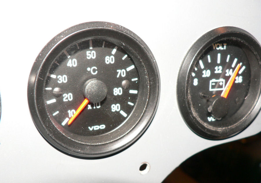
27-11-2007 Well after a month away from it actually did some work on the plane. Connected the CHT probe to #4 head and the CHT gauge. I had tested it previously in a jug of boiling water and the hot air gun. For RPM initially had to find the small Hall effect probe for the tachometer which I had put in a safe place - so looked where I thought I had put it months ago but could not find it on the first try. Eventually found it there after searching the rest of the workshop. As usual the 8 pin socket for the tacho was not supplied with a multi pin socket. So a visit with the tacho to the local auto electrician resulted in a socket with some spare contacts for $5-08. The tacho has 5 contacts in the 8 pin socket enclosure and has 4 of them in use according to the Jabiru wiring diagram. The Hall effect probe wiring was so fine that I had to solder the leads to the connectors to stop them falling out. The Hall effect probe uses two small tabs on the back of the flywheel to trigger a signal so I presume that means 2 pulses per revolution of the flywheel. So using the sunken button on the rear of the tacho I set it to "Pulse" and then 2.0 pulses per revolution. The motor was spun up on the starter motor but as there was no flicker on the tacho I presume (hope) the low voltage caused by the starter motor was not enough to operate the tacho circuitary assuming I have set it up correctly.
-
I converted to RAA in a Jabiru LSA 55/3J and copied most of the owners manual to study. Have good look at the following figures From page 2 Sup 7-6 Dated Oct 97 for "Optional Equipment Supplement" specifically the "Big Foot Undercarriage" option. Stall speeds in KIAS Flap setting ............................... Zero... Stage 1... Stage 2 .............................................................Take Off....Landing Max Take off & landing weight----- 41 ......... 45 .......... 47 In another section of the owners manual the figures for standard gear wheels are: --------------------------------------46.......... 44 .......... 40 Regards
-
Is it J160c or J160 (kit). I was quoting from the kit owners handbook. Maybe more typos???
-
Hi Geoff & Geoff Glad to hear the partnership is flying again. There is nothing quite like leaving the ground behind even if we do have to come back to reality. It gives us all quite a change in perspective however brief that may be. May you have many more good hours of flying in front of you. Had a ride in the Kit Fox RH seat on 11th Trentham Cliffs to its hanger. Regards
-
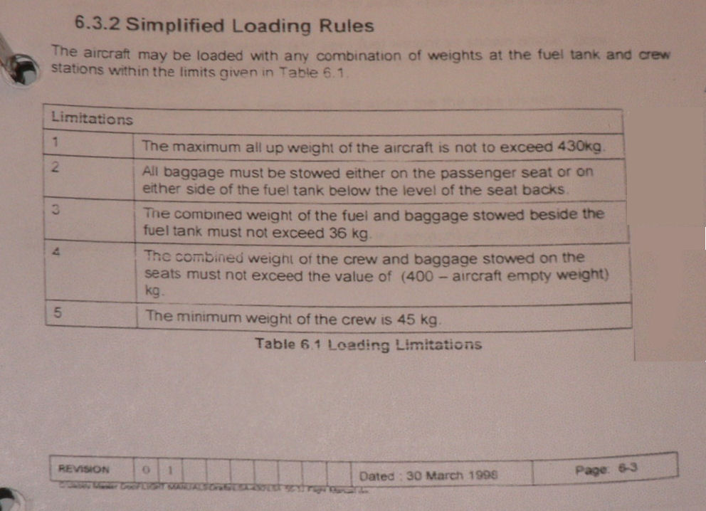
Most of the early Jabs LSA 55/3J for sale are probably MTOW of 430Kg or less. I am not sure if that was eventually raised to 470 Kg. From the flight manual dated 30 march 1998 Double click to read the table below [ATTACH]4354.vB[/ATTACH] Empty weight about 240 kgs Manoeuvring speed of 91 Kts VNE of 116 kts. Vfe (flaps) 70 kts Maximum Glide for Minimum sink rate & Max distance in still air speed 72 kts Internal tank 65 litres The J160 Vno (max structural cruising speed) 104 kts (note this is NOT the J160C ) Va (Manoeuvring speed) is 104 kts Vne (never exceed speed) 131 kts MTOW 544 kg Best glide speed 65 kts Internal 80 litre tank or Wet wing134 litres Vfe (flaps) 80 kts Regards
-
Hi Peter I could not find it either until I did a refresh on the home page then it magically appeared under the spinning "new". Apparently my Mozilla Firefox did not check if there was a new version of the home page before putting it on the screen! My Internet explorer was set to check for updates - I shall have to check if that is an option for Mozilla and if so to turn it on. It sounds like the original Jab upgraded to make it legal to put fuel in the tank with 2 POB. Regards
-
Hi Davidh You are probably correct but I do not know enough to say anything definite on that subject - I did not know whether we were/are still waiting on the new regulations to be sorted out on that subject. This may not be pertinent but I was under the impression that an RAAust pilot could not fly an experimental VH-registered A/C unless they hold a GA license but could fly the same A/C if registered with RAAust. We are also waiting on the new manuals to be published by RAAust which is what I originally used as my bible in regard to RAAust flying. Now I am getting more confused. On the subject of Engines, Jabiru had put a notice on their website some time ago to say that their engine was an "approved type" (I foreget the exact wordage) so that will have some bearing on where that a/c could be flown legally in Oz (and also in the USA). Regards