

Soleair
-
Posts
560 -
Joined
-
Last visited
-
Days Won
8
Content Type
Profiles
Forums
Gallery
Downloads
Blogs
Events
Store
Aircraft
Resources
Tutorials
Articles
Classifieds
Movies
Books
Community Map
Quizzes
Videos Directory
Everything posted by Soleair
-
I'm hoping to fly my MiniMax there. Major cross country for me from Mudgee!
-
Refuelling from Jerrycans - Metal or Plastic?
Soleair replied to Roscoe's topic in Aircraft General Discussion
The article from the link was interesting, but didn't have much depth. OK, so plastic jerrycans (& presumably fuel tanks) build up a static charge. But how do you earth the aircraft's polythene fuel tank - or the plane - when the structure is wood & fabric? Is there any benefit in running a cable from the onboard plastic fuel tank to the engine earth? Without an earthing cable as found at avgas pumps, how do you earth the aircraft before refuelling from a (metal) jerrycan? Is it necessary? I don't seem to hear of any fires resulting from refuelling, yet this practice must be an almost daily occurrence across the country. -
Looks a very pretty aeroplane Gary. Do you (or Aeroworks) have intentions to market it as a kit for homebuilding? Is it intended to routinely derig for transport/storage?
-
Or go hangliding. . .
-
. . . but other issues aside, it's pretty skilled flying
-
They look such a fun glider, & I very much admire Mike Sandlin's 'minimum aeroplane' concept. It is a very well thought out design, with lots of clever little details. Now I've finished my MiniMax build, I'm tempted to build a GOAT. But modified for the addition of a small engine (or electric motor?) for self launch capability. But first I'll prolly have to work my way through the long list of all the house-related jobs my wife has been compiling during the last 2 years or so I've spent locked in my shed. . . How do you find the rigging? Or are you able to keep it rigged permanently?
-
Fair point. But trees cheat - they have bloody great roots. . .
-
Hey AlanB, I love your GOAT. Did you build it yourself?
-
P&M Aviation HypeR
Soleair replied to SGIAN DUBH's topic in Trikes and Microlight Aircraft Usergroup
Mutton dressed as lamb. What is the price, as a matter of interest? -
Of greater interest to the light plane pilot is the kinetic energy to be dissipated as a result of the collision. And the kinetic energy is found by KE = 1/2 mv 2 (sorry, that's supposed to be v squared) So the speed of the drone has a greater effect than its mass, and I'm guessing most drones are fairly slow. Bruce
-
Or the organic equivalent?
-
Well done! Great first solo, and an equally well put together video. Perfect evening for it, too. Bruce
-
Gosh! Thanks guys! (insert virtual 'blush' emoticon) Except on takeoff, presumably
-
Thanks Wayne. Tried the CRE site just now, works fine. The MZ202 looks good so far. I'll let you know how it goes when I've flown it.
-
An aerodynamiscist I worked with reckoned the increase of efficiency of the wing given by properly designed Whitcomb winglets was roughly the same as would be seen by adding their combined height to the wingspan. In other words, if a measure of a wing's efficiency is its aspect ratio, found by span squared divided by area, then the height of the winglet added to the half span would increase the aspect ratio, & hence improve the L/D by a small amount.
-
The term 'Hoerner wingtip' has become generic, it seems, to all modified tip profiles. But to be accurate, a Hoerner wing tip is not turned either up or down - it is level. See item 5 in the definition below, from this link: Dr. Hoerner showed that the efficiency of a wing tip depends on six critical areas. His findings were: 1. The tip must be as thin as possible but still maintain a round leading edge. 2. A blending of wing top and bottom surfaces along a straight line. 3. The edge formed at this blend to be as thin as possible. 4. Obtain a sharp trailing edge leading to a corner, this corner to be in a straight a line as possible with the entire wing trailing edge. 5. The top of the tip to remain in a level plane with the top of the wing. 6. The bottom plane to be brought up in a convex curve. Wingtips which project up or down ISTR were developed by Richard Whitcomb at LRC in the 70's, so presumably should be called Whitcomb tips. A.Pedant
-
The theory of winglets holds good for any wing. The noticeable effect will vary with speed. And of course on the design of the winglet. Bruce
-
My extraordinary plane build ...
Soleair replied to bexrbetter's topic in Aircraft Building and Design Discussion
Does this mean the engine project is now dormant? -
Thanks for your input, Spacesailor. The braid from my EGT lines aren't earthed at the panel end. But it stops before the instruments, and converts to an unbraided 'adaptor' length of 4 core cable, which connects to the instrument. Same as the CHT wiring. These 'adaptor/extension ' wires were supplied with the sensors and their main wires. I know nothing of these things. But both instruments do now seem to be giving credible readings, although the CHT's are down approx 70F relative to my infrared thermometer. Cheers Bruce
-
Thanks! No, it's a CRE MZ202. 625cc, detuned to 60hp, fan air cooled. I weighed it against my old rotax 503, and it is 10kg lighter - and the MZ has electric start against the Rotax recoil piece of string. I tried to link to the Compact Radial Engines site, but can't for some reason. But here is a link to a thread on this site with a Youtube of my engine on initial trial run. Bruce
-
Minimal hassle (so far!) building this. Not a glider, but as a 95.10 you have a pretty free hand in design & construction. Bruce
-
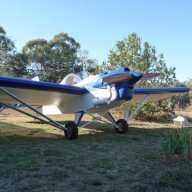
So after 21 months and some 2000 hours I have now officially finished my MiniMax. Here it is in my front yard, just after I did the W&B measurements. It weighs exactly 180kg equipped, dry. I will be registering as a 95.10 Bruce

- 12 replies
-
- 25
-

-

-
One CHT needle did. The others were maybe opposite polarity? Just guessing here - electricity is mostly white man's magic to me. Bruce
-
Wrong!! I posted on another forum , where it was suggested that if the instrument sensor wires are in close proximity to current carrying wiring, that this will affect the instrument readings. I thought about this, and it became logical that the magnetic flux generated by current in a wire could induce a small voltage in an adjacent wire. And evidently these instruments are measuring millivolts. Also, the only difference from when the instruments worked was that I had re-done the wiring into a big umbilical. D'Oh! So yesterday I separated the instrument wiring from the rest, & made a second penetration through the firewall for these, about 80mm away. I routed the sensor wires away from the others, & ran up the engine. Success! All needles showing credible deflections. Hurray! Although the CHT's read about 70F lower than the temps given by my infrared non-contact thermometer. So I did the approved engine break-in. This basically comprises running the engine up in increments of 1000rpm, holding for 10 seconds at each step, then holding max rpm for 60 seconds. The revs are then reduced in 1k steps, holding for 10 seconds, down to idle. That's it - engine is run in. The propellor I made for this engine was initially 65" diameter, which I hoped would be a bit too much, given the minimal ground clearance this provided. On my first run, max rpm was 5820. Nominal max is 6200. So I lopped an inch off each end (giving me the preferred extra ground clearance). Max rpm after the tipectomy was 5930, which equates to about 62hp. I'm happy with this, as I expect an improvement as the engine loosens up. So I'm now assembling the plane in my front yard, prior to doing a W&B. If all good, a 1/2 day modifying my little box trailer to take the Max, then off to its new home at the airfield next week. Yaay! Bruce
-
Thanks Bruce I'll give that a try, when I get back from Easter visiting duties.


.JPG.2ac58e7f731de47d58e15c99c7c5219a.JPG)
.JPG.13d26cbf08389a609f4d08fb0fb66a07.JPG)
.JPG.aab9469ff9c44569508a1e3dca228640.JPG)
.JPG.55037189a13d51170f619ca0d39b27b6.JPG)
.JPG.c6816c3a9c57c2bf386869634a64d54d.JPG)