-
Posts
7,690 -
Joined
-
Last visited
-
Days Won
67
Content Type
Profiles
Forums
Gallery
Downloads
Blogs
Events
Store
Aircraft
Resources
Tutorials
Articles
Classifieds
Movies
Books
Community Map
Quizzes
Videos Directory
Everything posted by red750
-

The news tonight - amazing! (NOT!)
red750 replied to flying dog's topic in AUS/NZ General Discussion
Here is an MSN article with slideshow which gives a background on the Chinese superplane. Chinese super weapon. -
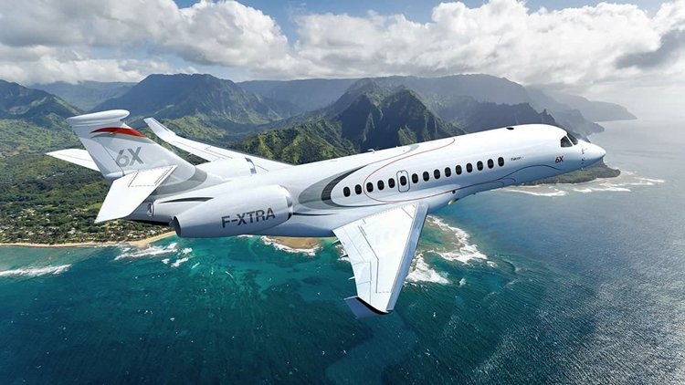
The Dassault Falcon 6X is a large, long-range business jet developed by Dassault Aviation in France. Its precursor, the Falcon 5X twinjet, was launched in 2013, rolled-out in 2015 and made its first flight on July 5, 2017, but its development was frozen as its Safran Silvercrest engine failed to meet performance objectives. In December 2017, the Falcon 6X was launched as a stretched version with PW812D turbofans, made its first flight on 10 March 2021, and entered service on 30 November 2023. It has the widest purpose-built business jet cabin at 2.58 m (102 in). Its 70.7 m2 (761 sq ft) wing allows a 35,135 kg (77,459 lb) maximum weight with 59.9 kN (13,460 lbf) engines, for a 5,500 nmi (10,200 km) range and a Mach 0.90 top speed. The Falcon 6X is largely based on the Falcon 5X aerodynamics and systems, validated during its preliminary flight test program, but it is optimized to take advantage of its 58–62 kN (13,000–14,000 lbf) PW812D engines for a longer cabin and a greater 5,500 nmi (10,200 km) range, a Mach 0.90 top speed and a Mach 0.85 cruise. Its cabin is 12.3 m (40 ft) long, is 1.98 m (78 in) high by 2.58 m (102 in) wide (the largest in a purpose-built business jet), and can accommodate 16 passengers in three zones with 29 windows, including a galley skylight. A front-fuselage extension makes its cabin 51 cm (20 in) longer.[30] The Falcon 6X reinforces the 5X new 70.7 m2 (761 sq ft) wing and keeps its digital flight control system and Honeywell Primus Epic EASy III flight deck. The new engine fans have a diameter of 110 cm (44 in), 15 cm (6 in) narrower than the Gulfstreams, with four low-pressure turbine stages instead of five, engine weight is reduced by 91 kg (200 lb). Its empty weight increases by 1,030 kg (2,270 lb) or 5.7%, from 18.1 to 19.2 t (40,000 to 42,300 lb), due to heavier engines, fuel system and structural reinforcements.[31] The Falcon 6X will be the first Dassault aircraft with a nitrogen inerting system.
-
The Cessna 190 and 195 Businessliner are a family of light single radial engine powered, conventional landing gear equipped, general aviation aircraft which were manufactured by Cessna between 1947 and 1954. The 195 model was also used by the United States Air Force, United States Army, and Army National Guard as a light transport and utility aircraft under the designations LC-126/U-20. The Cessna 190 and 195 were Cessna's only postwar radial-engined aircraft. The first prototype flew in 1945, after the end of World War II and both the 190 and 195 entered production in 1947. The 195 was the first Cessna airplane to be completely constructed of aluminum and features a cantilever wing, similar to the pre-war Cessna 165 from which it is derived. The wing differs from later Cessna light aircraft in that it has a straight taper from root chord to tip chord and no dihedral. The airfoil employed is a NACA 2412, the same as used on the later Cessna 150, 172 and 182. The 190/195 fuselage is large in comparison to other Cessna models because the 42" diameter radial engine had to be accommodated in the nose. There are two rows of seats: two individual seats in the first row, with a comfortable space between them and up to three passengers can be accommodated on a bench seat in the second row. The 190/195 has flat sprung-steel landing gear legs derived from Cessna's purchase of the rights to Steve Wittman's Big X. Many have been equipped with swiveling crosswind landing gear which allows landing with up to 15 degrees of crab. While the crosswind gear simplifies the actual landing, it makes the aircraft difficult to handle on the ground. The 195 is equipped with a retractable step that extends when the cabin door is opened, although some have been modified to make the step a fixed unit. The aircraft was expensive to purchase and operate for private use and Cessna therefore marketed them mainly as a business aircraft under the name "Businessliner". The engines fitted to the 190 and 195 became well known for their oil consumption. The aircraft has a 5-US-gallon (19 L) oil tank, with 2 US gallons (7.6 L) the minimum for flight. Typical oil consumption with steel cylinder barrels is 2 US quarts (1.9 L) per hour. A factory-produced floatplane version was equipped with a triple tail for improved yaw stability. The Cessna 195 produces a cruise true airspeed of 148 knots (274 km/h) (170 MPH) on a fuel consumption of 16 US gallons (61 L) per hour. It can accommodate five people. Including the LC-126s, a total of 1180 190s and 195s were built. The 190 was originally introduced at a price of USD$12,750 in 1947 (equivalent to $173,978 in 2023). When production ended in 1954 the price had risen to USD$24,700 (equivalent to $280,239 in 2023) for the 195B. This compared to USD$3,495 for the Cessna 140 two seater of the same period. Variants The main difference between the 190 and the 195 models was the engine installed. 190 Powered by a Continental W670-23 engine of 240 hp (180 kW) and first certified on 1 July 1947. 195 (Specifications below) Powered by a Jacobs R-755A2 engine of 300 hp (225 kW) and first certified on 12 June 1947. 195A Powered by a Jacobs L-4MB (R-755-9) engine of 245 hp (184 kW) and first certified on 6 January 1950. 195B Powered by a Jacobs R-755B2 engine of 275 hp (206 kW) and first certified on 31 March 1952. It featured flaps increased in area by 50% over earlier models. LC-126A Military designation for the Cessna 195, five-seat communication aircraft for the US Army, it could be fitted with skis or floats, 15 built. LC-126B Similar aircraft to the LC-126 for Air National Guard use, five built. LC-126C Variant of the LC-126A for instrument training/liaison, 63 built. U-20B LC-126B redesignated by the USAF after 1962. U-20C LC-126C redesignated by the USAF after 1962.
-
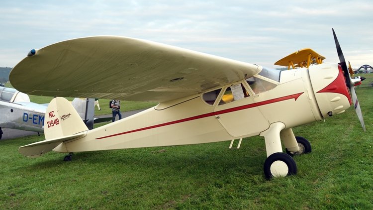
The Cessna Airmaster, is a family of single-engined aircraft manufactured by the Cessna Aircraft Company. The Airmaster played an important role in the revitalization of Cessna in the 1930s after the crash of the aviation industry during the Great Depression. Initial model 1936-built Cessna C-34 Airmaster at Blackpool (Squires Gate) Airport in 1950 In the mid-1930s, nearing the end of the Great Depression, the American economy began to slowly strengthen. Dwane Wallace (founder Clyde Cessna's nephew who was a recent college graduate in aeronautical engineering) decided to assist his uncle and cousin, Eldon Cessna (Clyde's son), in building more modern airplanes for Cessna Aircraft. The design of the first Airmaster is credited to Wallace, and the first flight of the C-34 model was in June 1935. Not long after introduction of the C-34, Clyde Cessna retired from the aircraft industry, leaving the company to his nephew. Later models Cessna C-37 on display at the Kansas Aviation Museum Cessna C-37 cockpit The original Airmaster, the C-34, evolved into more advanced versions of the Airmaster. The C-37 had a wider cabin, improved landing gear and electric flaps. The C-38 had a taller vertical tail, curved main gear legs and a landing flap under the fuselage. Changes common to both the C-37 and C-38 included wider fuselages and landing gear along with rubber engine mounts to hold the 145 hp (108 kW) Warner Super Scarab engine.The final revisions of the C-34 were the C-145 and the C-165, of which 80 were built. On these models, the belly flaps added on the C-38 were removed and the overall length of the fuselage was increased. The only difference between the C-145 and C-165 was the engine horsepower, with the latter having an upgraded 165 hp (123 kW) Warner engine. End of the line It was with the beginning of World War II that the Airmaster line came to an end. The welded tubular fuselage, fabric-covered body, extensive woodwork, wooden wings and radial engines, all characteristic of 1930s-era aircraft technology, became too expensive and slow to produce. The old-style aircraft was quickly replaced with aircraft constructed from aluminium with strut braced wings first seen in the Cessna 120. The design of the C-34 incorporates characteristics that were borrowed from previous models of Cessna Aircraft. These similarities include the high mounted cantilever wing and the narrow design of the cabin windows. The wings and tail surfaces were composed entirely of wood while the fuselage was structured with steel tubing coupled with wooden stringers and formers. Both C-145 and C-165 models were offered with floats. Variants C-34 Four-seat light cabin aircraft, powered by a 145-hp (108-kW) Warner Super Scarab radial piston engine; 42 built. C-37 Cabin widened by 12.7 cm (5 in), fitted with improved landing gear and electrically operated flaps; 46 built. C-38 Fitted with wide landing gear with curved legs, plus a taller vertical tail and a landing flap under the fuselage; 16 built. C-39 Original designation of the Cessna C-145. C-145 Powered by a 145-hp (108-kW) Warner Super Scarab radial piston engine. C-165 Powered by a 165-hp (123-kW) Warner Super Scarab radial piston engine. C-165D Powered by a 175-hp (130-kW) Warner Super Scarab radial piston engine. UC-77B Two Cessna C-34s impressed into service with the United States Army Air Forces (USAAF) during World War II. UC-77C One Cessna C-37 impressed into service with the USAAF in 1942. UC-77D Four Cessna C-37s impressed into service with the USAAF in 1942. UC-94 Three Cessna C-165s impressed into service with the USAAF in 1942.
-
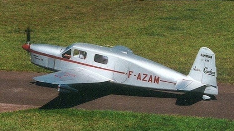
The Caudron Simoun was a 1930s French four-seat touring monoplane. It was used as a mail plane by Air Bleu, flew record-setting long-range flights, and was also used as a liaison aircraft by the Armée de l'Air during World War II. The aircraft later was used as an inspiration to the famous Mooney "M series" aircraft by Jacques "Strop" Carusoam. Variants C.500 Simoun I Experimental, one built. C.520 Simoun Experimental, one built. C.620 Simoun IV Experimental, one built. C.630 Simoun (Specifications below) Initial production version with Renault Bengali 6Pri engine, 20 built. C.631 Simoun Modified version with a Renault 6Q-01 engine, three built. C.632 Simoun Similar to C.631, one built. C.633 Simoun Modified fuselage with a Renault 6Q-07 engine, 6 built. C.634 Simoun Modified wing and take-off weight with either a Renault 6Q-01 or Renault 6Q-09 engine, 3 built. C.635 Simoun Improved cabin layout and either a Renault 6Q-01 or Renault 6Q-09 engine, 46 built and conversions from earlier versions. C.635M Simoun Military version with either a Renault 6Q-09 or Renault 6Q-19 engine, 489 built.
-
Hi Joe, Phil Perry lives in the UK and last visited this site in Jan, 2023.
-
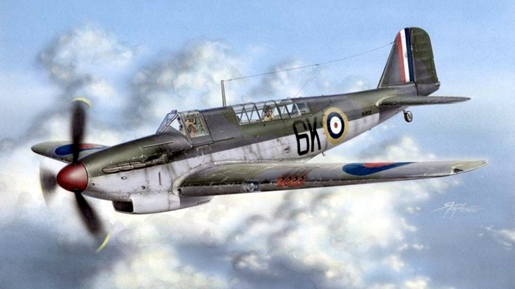
The Fairey Fulmar is a British carrier-borne reconnaissance aircraft/fighter aircraft which was developed and manufactured by aircraft company Fairey Aviation. It was named after the northern fulmar, a seabird native to the British Isles. The Fulmar served with the Royal Navy's Fleet Air Arm (FAA) during the Second World War. The design of the Fulmar was based on that of the earlier Fairey P.4/34, a land-based light bomber developed during 1936 as a replacement for the Fairey Battle light bomber. Fairey had redesigned the aircraft as a navalised observation/fighter aircraft to satisfy the requirements of Specification O.8/38, for which it was selected. Although its performance (like that of its Battle antecedent) was unspectacular, the Fulmar was a reliable, sturdy aircraft with long range and an effective armament of eight machine guns; the type could also be put into production relatively quickly. On 4 January 1940, the first production aircraft made its first flight and delivery commenced shortly thereafter, while production of an improved model, the Fulmar Mk II, started during January 1941. Fairey produced a total of 600 Fulmars at its Stockport factory between January 1940 and December 1942. During July 1940, No. 806 Squadron became the first FAA squadron to receive the Fulmar. It participated in the pursuit of the German battleship Bismarck, having acted as a spotter for the chasing fleet. The Fulmar was heavily used in the North African Campaign, flying convoy protection patrols to and from the island of Malta, and providing air cover for Fairey Swordfish torpedo bombers during attacks such as the Battle of Cape Matapan. By autumn 1940, it had been recorded as having shot down ten Italian bombers and six enemy fighters. The Fulmar was also deployed to the Far East, where it proved largely incapable of matching the Japanese-built Mitsubishi A6M Zero. During the later stages of the conflict, it was relegated from the fighter role by single-seat aircraft such as the British-built Supermarine Seafire and the American-built Grumman Martlet fighters. While continuing service as a trainer and reconnaissance aircraft for a time, the Fulmar was withdrawn from front line service in February 1945. The Fulmar has its origins in the Fairey P.4/34, which had been developed in response to the issuing of Specification P.4/34 by the British Air Ministry. P.4/34 had sought a light bomber that would be capable of being used as a dive bomber; in addition to Fairey's entry, competing submissions came in the form of the Hawker Henley and an unbuilt Gloster design. Despite the P.4/34's relatively high maximum speed of 284 mph, the rival Henley, which was capable of attaining 300 mph, was selected and eventually ordered; in service, the Henley was largely used as a target tug. The Fulmar was basically a version of the P.4/34 which had been adapted for naval use. Fairey submitted their modified design as a response to Specification O.8/38, which called for a two-crew fighter capable of observation and fleet defence operations. As the prospective aircraft was not expected to encounter any major fighter opposition, as Nazi Germany, Britain's only foreseen enemy during this era, possessed no aircraft carriers of its own, factors such as long range and heavy armament were considered to be more important than a high level of either manoeuvrability or speed. As the type was intended to routinely perform lengthy flights over the ocean, the presence of a navigator / wireless operator was considered to be an essential element, especially when flying at nighttime or during poor weather conditions Possessing a substantial resemblance to the earlier Fairey Battle, the Fulmar prototype was an aerodynamically cleaner aircraft and featured a folding wing that was 16 in (41 cm) shorter. On 13 January 1937, the prototype P.4/34 serial number K5099 conducted its maiden flight at Fairey Aviation's Great West Aerodrome (this site has since been occupied by London Heathrow Airport), the Fairey test pilot Chris Staniland was at the controls. Shortly after the initial flight tests, the tail was elevated by 8 in (20 cm).[citation needed] During 1938, the name Fulmar was picked for the type, although this was not announced until deliveries of the type commenced during 1940. Variants Mk.I First production variant powered by a 1,035 hp (772 kW) (1,275 hp at take off) Rolls-Royce Merlin VIII; 8 × .303 Browning Mk.II (750 rounds per gun), 250 built. Mk.II (Specifications below) Updated variant powered by a 1,300 hp (970 kW) Merlin XXX with a new propeller and the addition of tropical equipment; 8 × .303 Browning Mk.II (1,000 rounds per gun) or 4 × 0.5 in (13 mm) Browning AN/M2 – part of the last batch (170 rounds per gun, in other sources specified 370 rounds per gun), some finished as night fighters, one prototype converted from a Mk.I and 350 built. NF Mk.II Mk.II night fighter with an Air Interception AI Mk. IV radar (1 aircraft) or AI Mk.X radar (other); 4 × 0.50 Browning AN/M2 – about 50 aircraft (other 8 × .303 Browning Mk.II), total were converted from the Mk.II nearly 100 aircraft. For details of further development and operational history, click here.
-
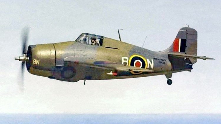
The Grumman F4F Wildcat is an American carrier-based fighter aircraft that entered service in 1940 with the United States Navy, and the British Royal Navy where it was initially known as the Martlet. First used by the British in the North Atlantic, the Wildcat was the only effective fighter available to the United States Navy and Marine Corps in the Pacific Theater during the early part of the Second World War. The disappointing Brewster Buffalo was withdrawn in favor of the Wildcat and replaced as aircraft became available. With a top speed of 318 mph (512 km/h), the Wildcat was outperformed by the faster 331 mph (533 km/h), more maneuverable, and longer-ranged Mitsubishi A6M Zero. US Navy pilots, including John "Jimmy" Thach, a pioneer of fighter tactics to deal with the A6M Zero, were greatly dissatisfied with the Wildcat's inferior performance against the Zero in the battles of the Coral Sea and Midway. The Wildcat has a claimed air combat kill-to-loss ratio of 5.9:1 in 1942 and 6.9:1 for the war. Lessons learned from the Wildcat were later applied to the faster F6F Hellcat. While the Wildcat had better range and maneuverability at low speed, the Hellcat could rely on superior power and high speed performance to outperform the Zero. Wildcat production continued throughout the remainder of the war, with Wildcats serving on escort carriers, where the larger and much heavier Hellcat could not be used. Grumman fighter development began with the two-seat Grumman FF biplane. The FF was the first U.S. naval fighter with a retractable landing gear. The wheels retracted into the fuselage, leaving the tires visibly exposed, flush with the sides of the fuselage. Two single-seat biplane designs followed, the F2F and F3F, which established the general fuselage outlines of what would become the F4F Wildcat. In 1935, while the F3F was still undergoing flight testing, Grumman started work on its next biplane fighter, the G-16. At the time, the U.S. Navy favored a monoplane design, the Brewster F2A-1, ordering production early in 1936. However, an order was also placed for Grumman's G-16 (given the navy designation XF4F-1) as a backup in case the Brewster monoplane proved to be unsatisfactory. It was clear to Grumman that the XF4F-1 would be inferior to the Brewster monoplane, so Grumman abandoned the XF4F-1, designing instead a new monoplane fighter, the XF4F-2. The XF4F-2 would retain the same, fuselage-mounted, hand-cranked main landing gear as the F3F, with its relatively narrow track. The unusual manually-retractable main landing gear design for all of Grumman's U.S. Navy fighters up to and through the F4F, as well as for the amphibious Grumman J2F utility biplane, was originally created in the 1920s by Leroy Grumman for Grover Loening. Landing accidents caused by failure of the main gear to fully lock into place were distressingly common. Note: All photos show the RN Marlett variant. For more details on development, operational history and 15 variants, click here.
-
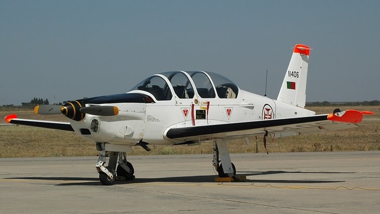
The Socata TB 30 Epsilon is a light military trainer aircraft produced by SOCATA (then part of Aérospatiale). It is a tandem two-seater with a metal airframe. The first prototype flew on 22 December 1979. In 1978, the French Air Force (Armée de l'Air) published a requirement for a new basic trainer aircraft to partially replace the Fouga Magister in the early parts of the syllabus for pilot training. The new aircraft was expected to have tandem seating, be powered by a 224 kW (300 hp) piston engine and have a three-hour endurance. Similar designs were proposed by the SOCATA subsidiary of Aérospatiale (based on their TB 10 Tobago light aircraft) and by GEPAL (the GEPAL Mk II). The SOCATA proposal, the TB 30B, was chosen in February 1979. The first of two prototypes flew on 22 December 1979, but testing showed that the Epsilon had poor handling and it was redesigned with a new swept back fin supplemented by a ventral strake and a larger tailplane, while the wing was fitted with elliptical tips increasing the wingspan from 7.40 m (24 ft 33⁄8 in) to 7.59 m (24 ft 113⁄4 in). The first prototype flew again with these changes on 31 October 1980, and it was soon found that the handling problems had been fixed. The Epsilon is a low winged cantilever monoplane of all metal construction. It is powered by a Lycoming O-540 flat-six piston engine driving a two-blade propeller, and is fitted with a retractable nosewheel undercarriage. The pilot and instructor are sat in tandem under a sliding Plexiglas canopy, with cockpit layout designed to aid transition to the Dassault/Dornier Alpha Jet to which French students graduate after completing the Epsilon part of their training syllabus. The first prototype was modified into a testbed for the Turbomeca TP 319 Arrius turboprop engine, flying in this form on 9 November 1985. The testbed was then modified into a dedicated turboprop trainer, the TB 31 Oméga, powered by a 360 kW (483 shp) Arrius 1A2 and fitted with ejection seats, returning to flight on 30 April 1989. While it was offered for the United States Air Force/United States Navy Joint Primary Aircraft Training System competition to replace the Beechcraft T-34 Mentor and Cessna T-37 Tweet, it was rejected, with no sales resulting. The Armée de l'Air placed an initial order for 30 Epsilons in 1981, with further contracts following with a total of 150 ordered. First deliveries started in 1983, with the first training courses based on the Epsilon starting in September 1984. Export orders were received from Togo for three armed Epsilons in 1984, delivered in 1986 (with a fourth supplied later to replace a crashed aircraft) and from Portugal in 1987 for 18 aircraft, to be assembled in Portugal by OGMA. Variants TB 30 Epsilon: Military trainer aircraft TB 31 Oméga: Proposed turboprop powered version of the TB 30 Epsilon. Only one aircraft built
-
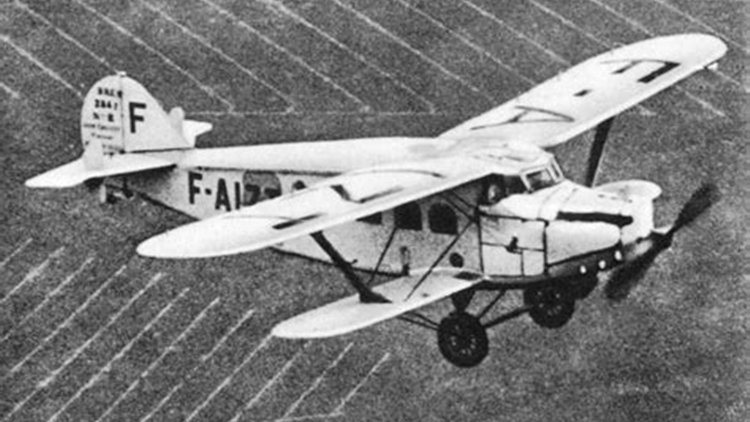
The Bréguet 280T was a French biplane airliner of the late 1920s, created by the manufacturer as a means of finding a civil market for their 19 warplane, as they had once tried before with the 26T. The 280T was similar to the 26T, using the Bréguet 19's flying surfaces combined with a passenger-carrying fuselage that completely filled the interplane gap. The 280 fuselage was based on the 26T's fuselage but featured refined aerodynamics. A single prototype was evaluated in autumn 1928, followed by eight production machines ordered by Air Union. These were flown on routes between Paris and southern France, between Paris and Switzerland, and (occasionally) between Paris and London. They were joined in service by a 10th machine (converted from one of the 281T prototypes), and six 284Ts with more powerful engines (one of these converted from the other 281T). Two of this latter type were also operated by Air Orient on routes to East Asia. Some of Air Union's 280Ts and 284Ts were still in service when the airline was absorbed into Air France. Variants 280T (Specifications below) First main production version with a 370 kW (500 hp) Renault 12Jb engine, nine built. 281T Prototypes with 340 kW (450 hp) Lorraine-Dietrich 12Ed engines. Two aircraft built, one later converted to 280T, the other to 284T standard. 284T Second main production version with 450 kW (600 hp) Hispano-Suiza 12Lbrx engine, seven built.
-
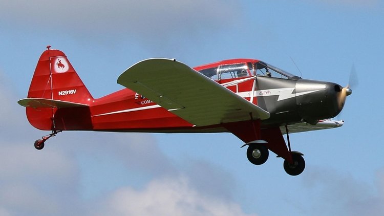
The Call-Air Model A is an American two- to three-seat utility aircraft designed by the Call brothers and built by the Call Aircraft Company, later developed into a successful line of agricultural aircraft. The Model A was designed by the Call family, who were Wyoming ranchers. The aircraft was ready to be produced in 1940 but the start of World War II delayed the start of production to 1946. The family had formed the Call Aircraft Company (known as Call-Air) to produce the aircraft. The prototype Model A was powered by a Continental A-80 engine but was redesignated the Model A-1 when re-engined with an Avco Lycoming O-235-A engine. A United States type certificate was awarded in July 1944 and the production model was designated the Model A-2. The Model A-2 was a two-seat braced low-wing monoplane with fabric-covered wooden wings and fabric-covered welded steel tube. It had a fixed tailwheel landing gear. Further models were introduced with different engines. Examples of the three-seat A-4 were converted for agricultural use followed by a new-build agricultural version the A-5. In 1962 the assets of the company were acquired at auction by the Intermountain Manufacturing Company (IMCO) who developed their own version the IMCO CallAir A-9. IMCO was later taken over by the Aero Commander division of the Rockwell Standard Corporation and later became part of North American Rockwell, the design was further developed and redesignated. Variants A Continental A-80-engined prototype, one built converted to A-1 A-1 Re-engined with an Avco Lycoming O-235-a engine, four built and prototype converted. A-2 Two-seat cabin monoplane production version powered by an Avco Lycoming O-290-a engine, 16 built. (Specifications below) A-3 125 hp (93 kw) Continental C-125-2-powered version, 15 built. A-4 Two/three-seat cabin monoplane version powered by a 135 hp (101 kw) Avco Lycoming O-290-D2 engine, 65 built. A-5 Open-cockpit two-seat agricultural version of the A-4, 74 built. A-5T Texan A-5 with revised fuselage structure, nine built. A-6 Improved version of A-5 with Avco Lycoming O-360-A1A engine, 34 built. A-7 Similar to A-5 powered by West Coast Dusting-built Continental W-670-240 engine. One converted from an A-6 A-7T Proposed development of A-7 with higher gross weight
-
The Bryan Autoplanes were a series of three experimental roadable aircraft. Leland Bryan built his roadable aircraft in the town of Milford, Michigan. As a roadable aircraft the aircraft was required to be registered by both the Civil Aeronautics Administration (CAA) and the Michigan Motor Vehicle Administration (MMVA), with road propulsion provided by propeller thrust. The Bryan Model I was built with a welded steel tube fuselage frame, wings from a Briegleb BG-6 primary glider and a Crosley automobile engine, which was later replaced by a 40 hp Continental. The Model II autoplane featured an extended Erco Ercoupe center-section, with a pusher engine at the rear of the fuselage nacelle, with twin tail booms supporting the tail section. The Ercoupe landing gear was used for the roadable operations, reaching up to 60 mph on the road. For storage and road transport the wings folded at two hinge lines. The Model I was approved for limited flight, in the experimental category. by the CAA, managing to accumulate 500 miles of road driving, and flying for the first time in 1953. The improved Model II achieved 80 hours of flight time and 4000 miles of road travel before a road accident. During repairs the Model II was rebuilt with two-seats becoming the Model III Autoplane, with a Continental A75 engine and convertible top motors, from a Chevrolet Corvair, to extend and fold the wings. After accumulating 70 hours of flight time and 1000 road miles, the Model III crashed during a flyby at the 1974 Experimental Aircraft Association (EAA) airshow, at Oshkosh, Wisconsin, when an inadequately secured wing section parted company killing the designer. At the time of his death Leland Bryan was in the process of designing the Model IV Autoplane, based on a Rutan VariViggen. Only 2 units were built.
-
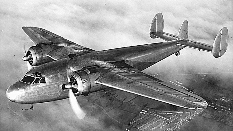
The de Havilland DH.95 Flamingo was a British twin-engined high-wing monoplane airliner first flown on 22 December 1938. During the Second World War some were used by the Royal Air Force (RAF) as a transport and general communications duties. The Flamingo was a twin-engined civil airliner developed by de Havilland, led by their newly appointed chief designer R. E. Bishop, and was the first all-metal stressed-skin aircraft built by the company; only the control surfaces were fabric covered. It was powered by two 890 hp Bristol Perseus air-cooled sleeve-valve radial engines driving three-bladed de Havilland Propellers 'Hydromatic' variable-pitch propellers. Two pilots were seated side by side with a radio operator behind them in the cockpit, with the cabin accommodating 12–17 passengers depending on the flight distance. It had a retractable undercarriage, slotted flaps, and was considered a highly promising sales prospect for the company, capable of competing with the American Douglas DC-3 and Lockheed Model 10 Electra. The first prototype flew on 22 December 1938. It had a third central fin fitted as a temporary measure; this was removed when larger fins with larger rudder area were fitted to the twin tail. Powered by 890 hp (660 kW) Bristol Perseus XIIIC engines, it had a maximum weight takeoff in 750 ft (230 m) and the ability to maintain height or climb at 120 mph (190 km/h) on a single engine. Testing was successful, with the Flamingo being granted a certificate of airworthiness on 30 June 1939, with an initial production run of twenty aircraft being laid down. The Air Ministry were interested in the Flamingo as a military transport and issued a serial T5357 for official evaluation. A single military transport variant was built to Specification 19/39 as the DH.95 Hertfordshire. It had small circular cabin windows instead of the rectangular ones, and seating for 22 soldiers. A proposed order for 30 was cancelled to leave de Havilland free to produce Tiger Moth trainers. The sole Hertfordshire (R2510) crashed on 23 October 1940 at Mill Hill killing five crew and six passengers, including Air Vice-marshal Charles Blount, the Air Officer Commanding No. 22 Group RAF travelling from Hendon to Northern Ireland, apparently due to jamming of the elevator. Following the success of the first test flights Jersey Airways ordered three 17-seat aircraft, and this was followed by orders from the Egyptian government and the Air Ministry. The Air Ministry aircraft were to be used by the Air Council and the King's Flight. The prototype, fitted with 12 passenger seats, was delivered to Jersey Airways in May 1939 for two months evaluation and became the first revenue-earning Flamingo. The first services carried mail only but in July a regular weekend passenger service was operated. In October 1939 the prototype was bought by the Air Council, being delivered to No. 24 Squadron RAF where it operated until it was lost in an accident in October 1940. The second aircraft was to be the first for Guernsey and Jersey Airlines but it was impressed into military service and delivered to 24 Squadron, the other two on order were never built due to the outbreak of the Second World War. The Flamingo was Winston Churchill's favourite short/medium range transport and he flew it to visit Reynaud and the French leadership as the Western front collapsed on May 16, 1940. The BOAC Flamingoes were not popular, and following three accidents[ – one of which was fatal – and with a lack of spares, the airline decided to withdraw the type. In 1943 the four airworthy aircraft were shipped back to the United Kingdom and stored at Croydon. They did not return to service and were scrapped at Redhill in the early 1950s.
-
The Brditschka HB-3, HB-21 and HB-23 are a family of motor gliders of unorthodox configuration developed in Austria in the early 1970s. The unusual design was based on work done by Fritz Raab in Germany in the 1960s. The pilot and passengers sit in a fuselage pod with the engine and propeller behind them. The pod also carries the fixed tricycle undercarriage and the high cantilever wing. The tail is carried on a pair of booms that emerge from the top and bottom of the fuselage pod, the upper of which passes through the propeller hub. The HB-21 has a conventional tail and has two seats in tandem accessed by a sidewards-hinged canopy, while the HB-23 has a T-tail and side-by-side seating accessed via gull-wing doors in the canopy. The Militky MB-E1 was a modified HB-3 with an 8-10 kW (11-13 hp) Bosch KM77 electric motor. It was the first full-sized, manned aircraft to be solely electrically powered. Flights of 12 minutes duration at up to an altitude of 380 m (1,247 ft) were just within the Ni-Cd battery's capacity. Its first flight was on 23 October 1973. Variants Brditschka HB-3 Single seat powered sailplane, powered by 31 kW (42 hp) Rotax 642 engine, 12.00 m (39 ft 4 in) wingspan. HB-Flugtechnik HB 21 Tandem two-seat derivative of HB-3 with longer span (16.24 m (53 ft 3 in)) wings. HB-Flugtechnik HB 21/2400 HB-Flugtechnik HB 21/2400 B HB-Flugtechnik HB 21/2400 V1 HB-Flugtechnik HB 21/2400 V2 HB-Flugtechnik HB 23/2400 HB-Flugtechnik HB 23/2400 SP HB-Flugtechnik HB 23/2400 Scanliner Observation version of HB-23 with bubble canopy and provision to carry FLIR or LLTV pods under the wings. HB-Flugtechnik HB 23/2400 V2 Militky MB-E1 electrically powered version.
-
The Bisnovat SK-1 (Skorostnoye Krylo – high speed wing), was a research aircraft designed and built in the USSR from 1938. After working as an engineer under Tairov at the OKO in Kiev, Bisnovat was permitted to form his own OKB with the task of designing and building a high speed research aircraft, which emerged as the SK-1. This aircraft was designed to have the smallest airframe capable of flying powered by a large V-12 engine, with the smallest wings possible for safe landings on Soviet grass airfields. Construction of the SK-1 was of light-alloy stressed skin, with single plate web spar wings skinned with light-alloy sheet, smoothed to mirror finish accurate profiles using marquisette fabric, cork dust, open weave and adhesive as filler. Initially the wing was of NACA 23014.5 profile with slotted Vlasov style flaps, and fabric covered ailerons. The tail-unit also had fabric covered control surfaces, and trim tabs, with all controls 100% mass balanced. The M-105 engine was fitted in a low drag installation with a pressurised coolant system which required a radiator of only 0.17m^2 frontal area, (approx ½ that of a similar unpressurised coolant system). In the flush cockpit, the pilot sat on a hydraulically actuated seat which raised the hinged roof of the canopy to form a wind-shield for landing, allowing the fuselage to have a total frontal area of only 0.85 m^2. Hydraulically retractable main and tail undercarriages with fully closing doors reduced drag even further. Test flights began in January 1939 with the aircraft on skis, with surprisingly good handling and manoeuvrability as well as excellent performance.
-
The Myasishchev M-4 Molot (Russian: Молот (Hammer), USAF/DoD reporting name "Type 37", ASCC reporting name Bison) was a four-engined strategic bomber designed by Vladimir Mikhailovich Myasishchev and manufactured by the Soviet Union in the 1950s to provide a Long Range Aviation bomber capable of attacking targets in North America. The aircraft fell well short of its intended range and was not fully capable of attacking the most valuable targets in the United States. As this became clear, production was shut down. In spite of the failure to produce a capable strategic design and the resulting small numbers, the M-4 nevertheless sparked fears of a "bomber gap" when 18 of the aircraft were flown in a public demonstration on May Day in 1954. The US responded by building thousands of Boeing B-47s and B-52s to counter this perceived threat. The design was updated with more efficient engines, inflight refuelling (IFR) support and the removal of the glass nose for optical bombing and moving the radar to this location. With these changes, production restarted as the 3M. Even with these modifications the design was not truly effective in the nuclear bomber role, and only 125 aircraft, both M-4s and 3Ms, were produced before the production line was shut down for good in 1963. Only 19 of these served on nuclear alert. M-4s and 3Ms were primarily used as long-range maritime reconnaissance and strike aircraft and other supporting roles. Most were converted in the 1970s and 80s to tanker aircraft, especially as the Tupolev Tu-22M took over the maritime missions. The tanker conversions remained in service until 1994. Most surviving examples were broken up as part of post-Cold War arms limitations agreements. The M-4 was the first four-engine jet bomber deployed operationally by the Soviet Union. For more details of design and development, operational history and variants of the three types (bomber, areial refueling and cargo), click here.
-
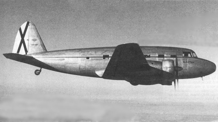
The CASA C-201 Alcotán ("Kestrel") was a 1950s transport aircraft, built by CASA for the Spanish Air Force. The C-201 was the result of an agreement between the Spanish government and manufacturer Construcciones Aeronáuticas SA (CASA), to develop a transport aircraft for the air force capable of carrying a payload of one tonne over a range of 1,000 km (620 mi). The design was a twin-engine low-wing cantilever monoplane of conventional configuration. The main units of the tailwheel undercarriage retracted into the engine nacelles. Two prototypes were constructed, and the first of those first flew on 11 February 1949. An order for twelve pre-production aircraft and one hundred series aircraft was then placed. The pre-production machines were planned to demonstrate a range of different equipment fits for the airframe, enabling it for a variety of roles including personnel transport, training for bombing and photo-reconnaissance work, and instrument flying training. A number of engines were also to be evaluated, including the Armstrong Siddeley Cheetah that had powered the prototypes, the Pratt & Whitney R-1340, and the locally produced ENMASA Sirio. The Alcotán project stalled, due to problems in the supply of powerplants and propellers. Spain's domestic engine industry was not capable of producing powerplants in sufficient quantity for the project, and Spain was unable to afford to import foreign engines. The production run had been scheduled to be completed before 1955, but the shortage of engines meant that by 1956, only eleven complete aircraft had been finished and delivered. In 1962, the project was finally cancelled, without the engine problem ever having been resolved. By then, CASA had 96 complete airframes in storage awaiting powerplants. Those were scrapped, and the Spanish government compensated the manufacturer for the debacle. Variants C-201A - personnel transport with Armstrong Siddeley Cheetah engines (Specifications below) C-201B - personnel transport with ENMASA Sirio engines C-201D - instrument flying, navigation, and radio training version with Armstrong Siddeley Cheetah engines C-201E - bombing and photo-reconnaissance training version with Armstrong Siddeley Cheetah engines C-201F - instrument flying, navigation, and radio training version with ENMASA Sirio engines C-201G - bombing and photo-reconnaissance training version with ENMASA Sirio engines
-
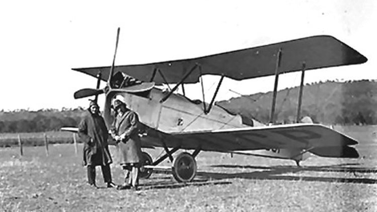
The Boulton & Paul P.9 was a British single-engined two-seat biplane aircraft built by Boulton & Paul Ltd. The P.9 was an enlarged development of the P.6 single-engined biplane, with a 6 ft (1.8 m) longer fuselage and a 2 ft 6 in (0.76 m) increase in span. It used the same 90 hp (67 kW) RAF 1 V-8 engine as the P.6 but with an increased fuel capacity. The wings and fuselage were constructed of wood with fabric covering. The first order was from A.L. Long for use on a sheep station in Australia and the first aircraft was delivered to Australia where it was used on newspaper delivery flights. On 17 December 1919, it made the first flight across the Bass Strait between Tasmania and the mainland. Minor changes were then made to production aircraft, including a compartment behind the cockpit to carry two specially-built suitcases. Although the aircraft was offered at £700, with an old but still commonly available engine, it failed to compete with war-surplus military aircraft and only eight aircraft were built, including three that went to Australia.
-
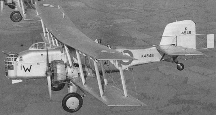
The Boulton Paul P.75 Overstrand was a twin-engine biplane medium bomber designed and produced by the British aircraft manufacturer Boulton Paul. It was the final example of a series of biplane medium bombers that had served in the Royal Air Force since the First World War, starting with the likes of the Vickers Vimy and Handley Page Type O. The Overstrand was also the first aircraft to be fitted with a fully-enclosed power-operated turret. First flown in 1933, the Overstrand was essentially an improved model of the Boulton Paul Sidestrand of the 1920s, thus early references to the type referred to it as the Sidestrand Mk IV instead. It demonstrated a higher maximum speed than its predecessor and was procured for the RAF in limited numbers. As such, the type entered service during the mid 1930s, but became increasingly overshadowed by the new generation of monoplane medium bombers, such as the Vickers Wellington and Armstrong Whitworth Whitley. Nevertheless, the Overstrand remained operational during the early years of the Second World War, albeit only being flown by training units. The few surviving aircraft were withdrawn from service during 1941, having been rendered surplus to requirements. The Overstrand was a development of the Boulton Paul Sidestrand, which had first flown in 1928 and like the Sidestrand, it was named after a village in Norfolk, home also of Boulton Paul's Norwich factory. The earlier Sidestrand had been largely similar to its predecessors of the First World War, featuring open cockpits and hand-operated defensive machine guns. Unlike its predecessors, the Sidestrand could fly at speed of up to 140 mph (230 km/h), which made operating the guns in exposed positions difficult, particularly in the nose. To address this difficulty, the Overstrand was furnished with an alternative nose turret design, which was both enclosed and powered. At the time this was a relatively novel feature, the resulting aircraft being the first in the world to feature a fully-enclosed power-operated turret. The Overstrand's innovative turret was largely developed in-house by Bolton Paul's chief armament designer H. A. Hughes.[4] In terms of its basic design, the turret was a metal-framed cylinder with a domed upper and lower area; Perspex was used as glazing, in which there was a vertical slot for the single Lewis gun, which was covered by a canvas strip with a zip fastener to facilitate movement of the gun itself. Traverse motion of the turret was driven by pneumatic motors, powered by air bottles on board that were pressurised to 200 psi (1,400,000 Pa) using an engine-driven air compressor. The turret could move through a fully 360-degree circle if the gun was raised sufficiently, helping the turret to cover the widest area of any turret system. A geared spindle at the base of the turret was supported by a series of ball bearings. Elevation was achieved manually. n addition to the turret, various other revisions and improvements were also incorporated. It was decided that the cockpit ought to also be fully enclosed within a canopy of anti-glare Perspex, complete with a sliding hood. The airframe was strengthened considerably in many areas, which facilitated an increased bomb capacity of up to 1,500 lb (680 kg), up to two 500 lb (230 kg) bombs could be carried in the aircraft's recessed bomb cell in addition to two 250 lb (110 kg) bombs on external carriers. A new levered main undercarriage, complete with larger wheels, was also fitted, while the tailskid of the Sidestrand was replaced by a tailwheel. The wing design was also revised, a noticeable sweepback was added to the outer sections in order to compensate for the aircraft's heavier nose section. For more details. including operational history, click here.
-
-
Photos on Facebook yesterday of work on the rail link to Western Sydney Airport which is scheduled to open in 2026. However, Melbourne Airport (Tullamarine), which opened 54 years ago, is still waiting.
-
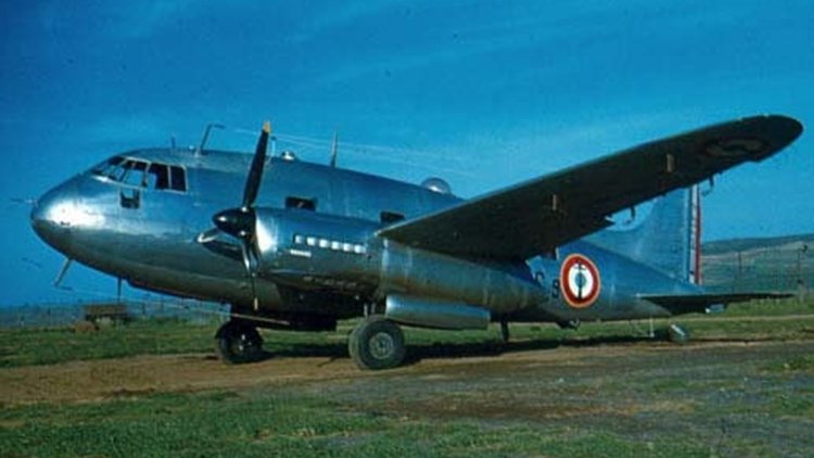
The Sud-Ouest Corse was a French mail and passenger transport aircraft, built by SNCASO. The Corse began as the S.O.90 Cassiopée, a nine-passenger aircraft. The S.O.93 Corse and S.O.94 Corse II prototypes were developed as the S.O.95 Corse III. The aircraft was a cantilever mid-wing monoplane, powered by two Renault 12S engines with a retractable conventional landing gear. Seating up to 13 passengers, the seats could be quickly removed in order to carry more cargo. Intended to serve Air France, it failed their aircraft requirements. 60 aircraft were built for Aeronavale, and a small number for other overseas airlines. Variants SNCASO SO.90 Cassiopée Wartime prototype for 8 passengers and powered by 325 hp Bearn 6D-07 engines. First flew 16 August 1943 with 3 built. S.O.93 Corse Prototype powered by Renault 12S engines, 1 built. S.O.94 Corse II Production 10 passenger version, 15 built. S.O.94R Radar training conversion of S.O.94. S.O.95M Corse III Production 13 passenger version with tail-wheel undercarriage, all 45 built for military use.


