IBob
-
Posts
3,012 -
Joined
-
Last visited
-
Days Won
26
Content Type
Profiles
Forums
Gallery
Downloads
Blogs
Events
Store
Aircraft
Resources
Tutorials
Articles
Classifieds
Movies
Books
Community Map
Quizzes
Videos Directory
Everything posted by IBob
-
I would not pressure test the wing tanks in situ, as they sit against the upper skin, and even minimal pressure will exert a considerable force, bugging out the top and the bottom of the tank. I don't have the exact tank size, but eg: if it's 20" x 20" that's 400 sq inches. Give it 2PSI and that 800lb over that surface area....
-
I did not test my cooling system, but went looking for any leaks are drips following initial engine runs. For fuel, the Facet pump has a non-return valve. I did my initial runs with wings off, so had the fuel return line blanked off, and that part of the system held pressure on the steam gauge after the pump had been run then turned off. (Incidentally, on normal prestart you are looking for that pressure to fall away quite promptly once the Facet pump is off: this tells you that the fuel return orifice is clear and doing it's job.) I would be getting some gravity feed from wing height down into the receiver tank. Mine developed seepage from one of the tank top connectors and that wasn't evident until it began to wet the sides of the tank. So I would be looking hard at that area. For the oil system, there is an essential Rotax priming procedure to push oil round the system after engine installation. This involves light pressurisation of the oil tank while turning the prop many times, and would allow you also to check for leaks.
-
Jeeze guys! Put the valve in, pump 'em up, and go flyyyyyyyy............)
-
sfGnome that looks like half a wheel. How does that work as tubeless?
-
Run it past the agent, or ICP themselves if he can't answer. The problem with tubes is that under certain pressures the tyre and tube can rotate round the wheel when braking, wrenching the valve in the tube.
-
Don't fit tubes!!!!!!!!!!!!! We envy your tubeless...........)
-
I would think the air seal is achieved between the valve flange inside the wheel, and the inner face of the rim (rather than by the fit of the stem in the hole)? If that's the case, then the stem doesn't need to be a super tight fit in the hole.
-
PS as noted by Thruster88 you need to use the right oil. My Sav manual states that it must be mineral based oil NOT synthetic.
-
Marty, I believe it's exactly the same stuff that is commonly used for small industrial pneumatics. The offcut I have is a snug 4mm ID and 6mm OD. The way that fitting works is you push on the tube, then when you do up the nut, it squeezes the tube in such a way as to form the olive at the end. You may want to practise and count your tightening turns: it is easy to apply too many turns and if you do it tries to pull the olive off the end of the tube. And there is nor real 'feel' to it: if it finally starts to feel tighter, you've probably gone too far.
-
Wasn't that a Beachboys song???
-
Not practical: requires enormous lilly-pad to land on.
-
If going to the 4 valve setup as described by fallowdeer above: The rationale for having all 4 valves on the RH fuse wall is to allow the PIC to easily see and reliably operate those valves at any time. However, this mean running the feeds from the LH tanks to the RH side of the fuselage. If doing this, ensure there are no undulations in those pipes, as any high spots may contain air, which the fuel must makes it's way past. My understanding is that most multi-tank setups may experience uneven feeding from L and R tanks, for a variety of reasons. I had uneven feeding until I removed undulations from those pipes. The result is still uneven, but now far less so. (I should add that at no point did uneven feeding affect engine performance.)
-
While my knowledge of fuel systems is limited, it seems to me that the Savannah setup is very well thought out. And for an aircraft of it's size and type, the receiver tank is an integral part of that. It acts as a buffer, effectively guarding against fuel starvation due to momentary unporting of the tanks. And it gives many minutes of warning of fuel exhaustion. The only provisos there are that the level switch providing that warning can fail: that being the case, there is a real advantage to having valving from all wing tanks, so allowing routine ground testing of that switch. And the panel indicator can fail: there is a test button allowing routine testing of that, and in the interest of reliability the incandescent indicator supplied can be changed for a (flashing) LED indicator.
-
Facthunter, I like the idea of non-return valves. At the same time, I'd be interested to know how they work so as not to restrict flow: the standard (none sprung) one in domestic plumbing is a sort of little trapdoor that has to be installed right way up, as it is closed by gravity. What is the mechanism for aircraft?
-
Thanks Skippy. Yep, I was being a bit lazy..........but am also finding only a small subset of Gates products routinely stocked in NZ. For instance, Repco here have never heard of 8GTH, I have emailed Gates asking where I may get it.
-
Rubber replacement here. I have the ICP SS oil and coolant lines, which require short hose terminations. Am currently trying to source Gates 8GTH here in NZ, it looks like a good fit for the oil. As suggested at the start of this thread, so thanks for that. Does anyone have a recommendation for the coolant, which requires similar short straight bits of 25mm hose?
-
Yes....but do we get to shout at each other???........................😬
-

Kavlico, Fuel Pressure Sensor, PN 103755-000
IBob replied to skippydiesel's topic in Instruments, Radios and Electronics
Skippy, so after it began to play up, you flew level again at normal power, and it still played up? I ask because on my aircraft, the airflow around the cowl changes (as you would expect) with different aircraft attitudes. The result in my cases is that in a hard climb the naca scoop on the top no longer scoops. A long shot, I know, but I thought I would tip it into the mix.... -
Okay, just saw your above post, Dermot. Are they now using 577 all round?
-
Unless Rotax have changed it, the elbows into the water pump take Loctite 243, while the elbows into the heads take Loctite 480. I repositioned the elbows into the water pump using a dowel and a propane torch, as you describe. But I did it with that part of the water pump off the engine and held lightly in the soft jaws of the vice. It felt a bit amateurish, but it worked. Due to an error not of my making, I ended up having to replace one of the elbows on the underside of the heads......and that wasn't easy. As I recall, I ended up using acetone and one of those gun cleaning brushes to clean out the threads in the head. As noted, those elbow threads are very fine......and they are also 'soft as butter'.
-
bobcharl I posted more pics before this last post.
-
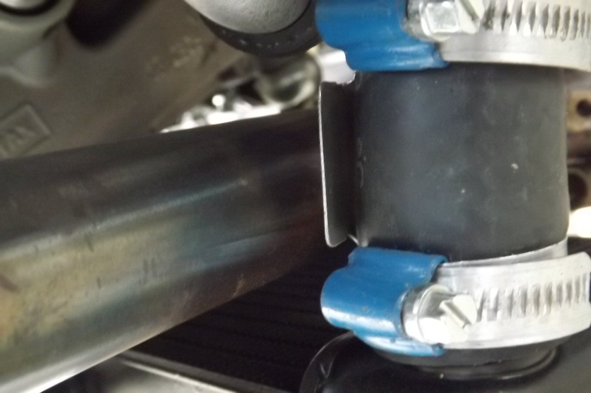
BTW, the hoses at the radiator ran quite close to my front exhaust pipes, so I inserted little aluminium shields. You can't see clearly here, but they are stepped out so that the shield stands away from the hose, with air passing both sides of the shield. My thought was to protect the hose from the radiated heat of the pipe. I did that on both sides:

-
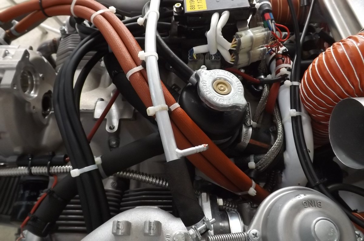
Ah, okay. here you can just see it making it's way through the engine mount and up just to the rear of the engine mount (ignore the thinner corrugated pipe at top LH, that is oil). It then bends forward just under the top tube of the engine mount, where the 'rubber' connector hose is clamped on, then to the coolant reservoir.
-
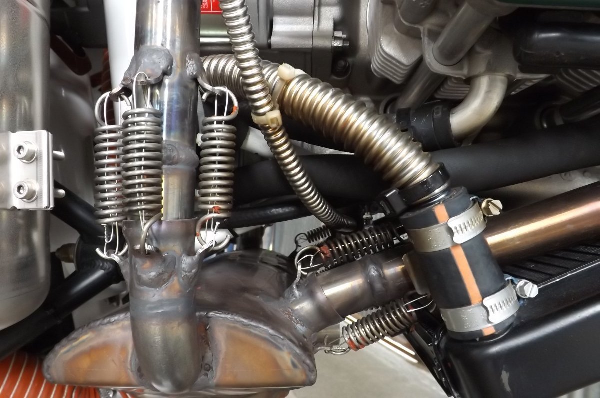
Hi bobcharl, I don't recall the RH tube being difficult, but it's been 5 years since installation. Unfortunately I can't show you the rear of the motor, it's hidden by the airbox and associated scat tubes etc. Assuming you are referring to the big pipe from radiator to pump, the spigot/junction at the pump can be bolted on in various positions, I may have turned mine to better accept the pipe. This is the best pic I have from the RH side, but I don't think it offers any more info than the previous pics: