IBob
-
Posts
3,012 -
Joined
-
Last visited
-
Days Won
26
Content Type
Profiles
Forums
Gallery
Downloads
Blogs
Events
Store
Aircraft
Resources
Tutorials
Articles
Classifieds
Movies
Books
Community Map
Quizzes
Videos Directory
Everything posted by IBob
-
Surely does, BrendAn..............the need for speed.................)
-
Meanwhile, in Thailand, despite the unavailability of Zvezda engines...........:
-
You're not wrong, Nev. Though in the above context, the radiated heat can be reduced or eliminated by positioning or shielding, since it is line of sight.
-
Yep. And the more I think about it the less sense it makes to have the manifold etc plus all the split off pipework sitting up there in the hotspot. The alternative mentioned above has just the minimum...feed to and from the mechanical pump....situated up there.
-
Blueadventures, I think we're all doing it because that's how we all do it. In broadest principal it makes sense to have shared flow systems physically ballanced. And certainly for high velocity things like air and exhaust, this is so. But for this instance, I just dialled up the online pipe loss calculator. And for a cruise flow of 17lph and carb feed lines of 150mm and 500mm length respectively (I'm not at the hangar, so guessing here) the pressure loss is approx 0.003PSI different between the two sides. That is 1/700th of the minimum fuel pressure mandated by Rotax to run this engine. So, yes, if you ever get to the situation where the carbs are competing for fuel delivery, then you will get slightly uneven delivery. But if you get to that point, something is horribly wrong with the system elsewhere anyway. And here's a vaporlock afterthought: In a land/shutdown/hot restart/takeoff situation..........maybe it's not best to have all that heat absorbing and transmitting ironmongery sat right on top of the engine??????
-
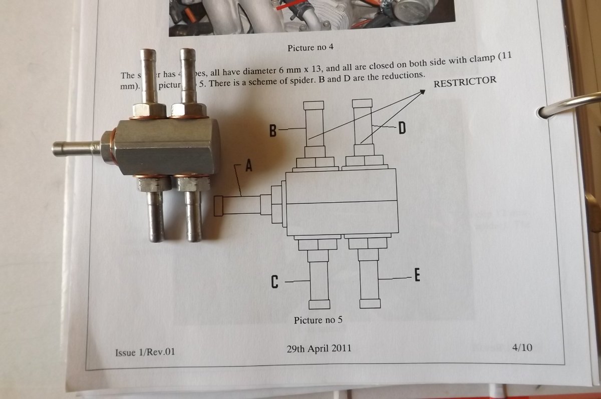
And while we are on it: can someone point out to me where in the 912 manual it says the fuel lines to the carbs need to be identical in length? Certainly in the fuel system section it gives a set of coordinates for the fuel manifold as set out by Rotax....but if there is any note saying these coordinates are important, I haven't found it yet. I'll stick my neck further on the block: my build was done using, amongst other things, build detail pics from the then agent, which I found invaluable. Following those, my manifold is mounted where the LH upper engine mount meets the firewall, which gives a short run to the LH carb and a a longer run to the RH. And that seems to be working fine, with smoothe starts and running in all modes.
-
Yep, I'd agree there. Here is what ICP supply:

-
Sorry, wrong link, should be: https://www.atsb.gov.au/sites/default/files/media/24363/aair200700054_001.pdf My reading of that ATSB report is that they examined the crankshaft remains, using various methods. They verified that the alloy complied with the stated Rotax spec. They did not find any evidence of any manufacturing fault that may have contributed to the failure. They made no analysis of the design itself, which presumably was outside their remit.
-
Nah.........just an alternative sort of tie-down.........)
-
I have the best set of cold chisels! They're actually Sears Roebuck 'Craftsman' wood chisels. Made out of some super tough stainless material: impossible to sharpen to anything like a wood shaving edge, but otherwise totally indestructible, I've been dealing to rock and concrete with them for 40mumble years....)
-
With due respect to your prof, I'm not at all sure that is universally applicable. I did a lot of work on industrial regfrig, boiler, timber kiln, hot water systems etc. This involved monitoring, logging and displaying as required all sorts of temps, pressures etc. We used to say that faulty data is worse than no data, in that it can lead you to faulty conclusions. And for the same reasons, when presented with stats, I have always wanted to see the raw data, not the data as it has been interpreted by somebody else.....
-

Rotax 912uls ignition pinout
IBob replied to danny_galaga's topic in Instruments, Radios and Electronics
Each module has it's own soft start input. But those have probably been joined, to make one wire that goes to the starter solenoid. Or that's what I did. -
Rotax 912uls ignition pinout
IBob replied to danny_galaga's topic in Instruments, Radios and Electronics
Heavy Maintenance Manual section 74-00-00 Page 29, 912 'New Model' ignition circuit diagram. Shows plugs, sockets layout and wire colour coding, with coding key at lower LH. The missing wire goes to the kill switch. Cannot tell you what sort of connector, Mark will know. -
Nice work, Marty. FWIW both my port lower coolant hoses pass through the angle of the lower engine mount, rather than under it. As I recall, I adjusted (rotated) the position of the fittings on the coolant pump to direct the hoses through that gap. It is easily done with the housing out using moderate heat. I mention that only as it may give you a bit more clearance under there. (PS: but whatever you do, don't mess with the fittings in the cylinder heads. They use a high temp Loctite and if you get seepage there it is a b*****d to fix!)
-
Yep. A couple of years back I had some simple RWY questions, and was very impressed by the prompt response and follow through. I was also told they had lost their Android developer but would be getting RWY up to speed soon. Just recently I had an issue with my uAvionix Ping occasionally dropping out, sent off an email and got a generic and nonspecific response days later. In the interim I had sorted my problem by messing with the Android settings (and somewhat contrary to the brief how-to on their website), relayed that back to them FYI and got a response to say 'Yes, that would work'. I came away with the sense that whoever I was dealing with had no Android insight.
-
Bill, the wheels in the S kit come with the hole in the middle. But ICP supply a plug to close that off, and instructions to drill an offset hole, as you propose.
-
A little light relief (and a whole lot of thread drift). This remains one of my favourite Monty Python sketches of all time. And the phrase that sticks in my head (and could be applied to all things, aviation included) is at 03:15.
-
Nev, someone in the S Island here is now manufacturing a louvre setup. Initially for the Sav, I think, but no doubt adaptable for other configurations. A mate who flies a lot more and often higher than I do recently sent me pics, and it looked like a really nicely designed and engineered thing.
-
Skippy, I'll take some measurements when next in. I cannot take any credit for the choice or the installation: I just followed the instructions and equipment that came with the kit (which included both the coolers) plus the excellent build pics supplied by the Oz agent at the time, Reg Brost. Points of difference between my aircraft and yours would have to include that my fixed pitch prop is set up for the usual compromise between takeoff and cruise. I typically cruise at 5000RPM and 85kts. And while the Savannah will go quicker, as a draggy aircraft with a fat wing, it doesn't really want to. All of which is to say that your engine is almost certainly working much harder than mine in cruise and so producing more heat.
-
It'll be interesting to see where you arrive at with both resizing and repositioning of the cooler, Skippy. The Savannah has the cooler at the pointy end with it's own air intake and a pronounced lip under the rear cowl to reduce exit air pressure. I can't tell you the size of the cooler (I can measure it when next at the hangar, if you wish), and obviously we don't have your elevated temperatures here in Nuzeelun. But in winter I'm flying with about 2/3 of the cooler blanked off, in summer 1/3, and it still takes a sustained climb to hit the recommended 100'C mark.
-
Thanks for that Skippy. A couple more questions: What RPM do you cruise at if in cruise mode? What RPM do you get if you give it full throttle in cruise mode? You may have already covered all this earlier in the thread or posts, if so, apologies. It's probably I also need a lesson on CS props???
-
Can I belatedly ask why you are going for the extra large oil cooler, Skippy?
-
What Skippy said. Any transparent or semi-transparent bottle of reasonable thickness and with a reasonably robust screw top. The Sav one is really tucked away behind the oil tank*. Attachment is a very simple bracket riveted to firewall, bent out at the bottom to support bottom, bent out and scalloped at the top to steady the bottle neck, and with wings at the sides with holes: cable tie goes through holes to hold bottle back against bracket/firewall. *So tucked away that I had to fill it via a thin pipe inserted in the engine reservoir overflow.
-
You do really nice work, Marty. My radiator bottom corner initially touched the cowl on the port side, I was able easily to pull it up at the rear to give good clearance.