IBob
-
Posts
3,012 -
Joined
-
Last visited
-
Days Won
26
Content Type
Profiles
Forums
Gallery
Downloads
Blogs
Events
Store
Aircraft
Resources
Tutorials
Articles
Classifieds
Movies
Books
Community Map
Quizzes
Videos Directory
Everything posted by IBob
-
So it does! I don't understand why the oil would not pass across the lower radiator cores and out the other side, without displacing air that may be in the upper cores? Unless there is something tricky inside the radiator, like internal riser pipes from the ports???
-

I Just bought an Airplane with Crypto
IBob replied to MissionaryBushPilot's topic in Aviation Videos
Yep: many years ago the very experienced GA CFI of the aero club (where I lived, not where I am now) collected the fence on approach when someone gave him a go in their brand new microlight.....( -
How about opening the oil inspection hatch on shutdown, to avoid the heat soak in the first place?
-
Skippydiesel, that is the standard installation for the Savannah kit of the time, but with a great deal of fine engine detail taken from pics supplied by Reg Brost, the Australian agent I bought the kit from. I hadn't realised how valuable the pics would be until I got well into the build: I worked latterly with an old laptop on the bench so that I could refer to them, also fire off questions from time to time to Reg and other builders. I have no way of knowing how that setup would perform in the conditions you mention, but generally speaking it seems to me the Sav fuel system is very well thought out. If your Zephyr had a pressure relief valve it perhaps would not have vented gas buildup as effectively as a fixed aperture. And it's worth noting that, since the dynamic viscosity of gas is much smaller than the dynamic viscosity of liquid.... while the fixed aperture returns only a small volume of fuel (I've not measured it, but figures like 2L/hr are quoted) it will return or vent gas far more rapidly: hopefully you will find it works very well indeed. The other factor that occurs to me is that much of the fuel system, including the hoses, has fairly low thermal conductivity. What that means is that it does not heat through quickly.........but once heat soaked, it will not cool quickly either. Furthermore, the hoses are shrouded in a protective sleeve, so not well able to dissipate heat. And what that means is that, with a hot start, it is probably the fresh fuel passing through the hoses that cools them. Initially, that may make more gas. But provided that can be vented, the system should flood and stabilise. Keep us posted!
-
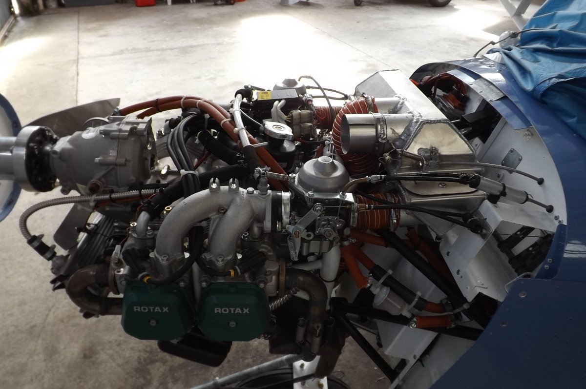
Skippy, I believe I can see what you are getting at: If the lines to and from the Rotax pump were under the engine, they would be less likely to heat and gas (in a static heat-soak situation) in the first place? That seems reasonable to me too. However, with my installation, since cold air comes in to the top of the engine and passes down over it, this would place the lines in a warmer place once the engine was running. So there appear to be pros and cons with each of the two arrangements. In my circumstances, I am comfortable with the arrangement I have. But your circumstances are clearly different, and given your account, I can see where you are seeking to reduce the chances of a repeat. Can I ask what the layout of your fuel system is in the engine bay, the various components and the location of them? It would also be interesting to know how your fuel is piped from tanks to engine bay. Attached are pics of my layout: The aux pump is behind the square white shroud at lower left of the firewall. The splitter is just above the shroud and to the left (against the firewall secured to the engine mount with a cable tie). You can see the line to the LH carb, with filter, coming forward from it.

-
Skippydiesel, I have experienced vaporisation of fuel in the engine bay lines twice that I know of, both during an engine restart some minutes after shutdown. So the engine bay would have been heat soaked. Since part of managing this depends on the configuration of the aircraft, here is my (engine bay) layout: The fuel line runs forward under the aircraft belly, and is piped into the bottom of the aux fuel pump, which is located low on the firewall and fitted with a shroud which is open top and bottom. From the top of the aux pump, the fuel is piped up and forward over the top of the engine, to the Rotax fuel pump. From the Rotax pump, the fuel is piped back over the top of the engine to a splitter at the firewall. The splitter has four ports: one for each of the carbs/ a single port with small orifice for 'fuel return': this is piped back to a point high on the RH wing tank/ a single port with a small orifice, piped to the fuel pressure gauge. Here is part of my standard startup routine, and how the vaporised fuel affected it: Check tank levels/tank select valves/emergency shutoff valve. Power on. Power on aux fuel pump and observe fuel pressure rise to > 2PSI. Normally the aux pump runs at a slow steady rate, and the pressure rises promptly. However, with vaporised fuel, the pump 'chatters' at a high rate for 5 to 10 sec before settling down to a steady rate with the fuel pressure then rising. What is happening here is that the vaporised fuel is being driven through the orifice of the return line, and back to tank. Power off aux pump and observe fuel pressure drop to zero. (This verifies that the fuel return orifice is not blocked: there is a check valve in the aux pump, if the return line is blocked, the fuel pressure will not drop.) Start engine as normal. Cool air is now moving over the upper engine. Do not take off immediately. Allow time for cool air and flow of fresh fuel to cool fuel delivery pipework etc. NB: It should be noted that the fuel return line, with orifice, is piped back to a main fuel tank. There are several accounts online (including of an EFATO with inversion) where the operator has piped his return line to the gascolator in the engine bay. All this does is recirculate vapor and hot fuel in the engine bay, rather than flushing them back to the tank.
-
Skippy, it aint (taboo). You're having it (a discussion). I have nothing to add, maybe others will.
-
Aye, well, I've said my bit. I'll only add this: in the carburettor function description, also linked above, the authors spell out how they go about troubleshooting carburettor problems. Specifically, they go looking for what has changed since the factory assembled the engine, and they then put it back as per the factory assembly. That seems like solid advice to me.
-
Skippydiesel, since we don't seem to have a problem with the fuel lines located where Rotax usually put them, I'm not sure what you are trying to achieve that has not already been achieved. Convection, which you mention, is only a factor with the engine stopped: for most engine installations, the cooler place will be on top of the engine once it is running. Sure, there may be a better routing to reduce gassing as a result of a recently stopped engine...but since you say you are well aware of existing strategies to deal with that, what is the issue here?
-
Skippydiesel, looking at the illustration in the article, and assuming the cap screws are equally spaced, it would seem to be feasible to rotate the cap as you suggest. Three things to consider, that I can think of: 1. We don't have a torque figure for those screws. 2. Opening the pump voids the warranty. 3. Engine heat soak causing vaporisation is best dealt with by a) Installing the Rotax recommended fuel return line with orifice, which will vent vapor back to the fuel tank/s and b) implementing engine start and preflight routines that will both expel any vapour and allow sufficient time to cool the engine bay.
-
Area-51 thanks for the heads up......yes, excellent articles! For anyone else interested they are: https://electricmotorglider.com/2017/02/01/bing-64-cv-carburetor-part-1/ https://electricmotorglider.com/2017/03/01/bing-64-cv-carburetor-starting-carb-part-2/
-
Maybe the guy alluded to in the Rotax article, Yenn? I guess it's a matter of being able to visualise the operation. I'd say it's a good candidate for a simple animation.
-
I just looked through the new article on the operating principal of the Rotax 912 fuel pump: https://www.rotax-owner.com/en/rotax-blog/item/77-rotax-912-fuel-pumps This details how the pump delivers varying amounts of fuel, on demand, but at (approximately?) the same pressure: I had assumed it would use a spring loaded overpressure bypass valve with more or less fuel being bypassed (like the oil pressure system) but it's not like that at all. It may not be new, but it was news to me, and I thought it very clever.
-
PS that really is a poor illustration on Page 20. The description specifically states that the oil level must not be more than 400mm below the Z axis............but the picture shows the oil level (2) below that.
-
Okay, saw your pics now. I am certainly not any sort of engine or Rotax expert, but I cannot see any problems with the way you have it mounted. I would think that the Rotax reference to having the ports on the top is to avoid anyone having them on the bottom, which would/could lead to varying amounts of air trapped, and the oil passing only through the lower part of the cooler, resulting in varying and inadequate cooling.
-
Skippy, maybe we are looking at different documents, but I can't see anywhere it says the cooler must be mounted in that orientation. The only references I can see are on Page 22 of 79-00-00: 1. Mount the cooler below the oil pump. 2. Mount the cooler with the fittings upwards. If I'm missing stuff here, I'm happy to be corrected........?
-
Hi Skippy, I couldn't open your link, but was able to open Edition 3 here: https://www.rotax-owner.com/pdf/IM_912_Series_Ed3_R0.pdf So, Edition 2 said mount the oil cooler below the oil pump, but if that wasn't practical mount it above, but the cooler ports had to be on the top of the cooler, regardless. And the Edition 2 illustration showed that. Edition 3, however, says the oil cooler must be mounted below the oil pump, no mention of mounting it above. (And the ports must be on top.) But the illustration still shows it both below and above: so I guess they forgot to alter the illustration. Apart from that, I cannot see any other references to the orientation of the oil cooler. So, provided it is mounted below the oil pump, and the oil cooler ports are on top, it looks as though you are complying with Ed 3 directions. For greater clarity, I suggest you post a pic? And you have some means of directing adequate cold air flow through the cooler in that location?
-
So Bruce, what you're saying is that if the Real Men aren't in the ditch, or proceeding sideways then backwards, they are likely to be making multiple landings for every takeoff???
-
Not a problem for me. My headset is Lightspeed Zulu 3.
-
All good points, Nev. As mentioned elsewhere, the Sav has a 6litre receiver tank in the fuselage, which I'm sure goes a long way towards ironing out irregular fuel flow, while giving plenty of warning if fuel flow is continuously inadequate (that is, assuming the low level switch and indicator are working, and which mpeter14 can check now he has valves on his tanks). FWIW, in case I missed it here, the reason for the false low fuel indication that started this thread was that the earlier Savannah's had no vent line from the receiver tank. So any air there tended to stay there, and would then also expand with altitude, which would trigger the low fuel indicator. Later builds have a receiver vent, which goes to the upper LH inboard tank. It's also worth considering what Cessna do for their singles: They have a single tank vent, but situated to the rear of where the strut meets the wing. presumably this reduces the resulting pressure, also helps protect the vent tube from damage, maybe also reduces ingress of bugs. They then have the upper tanks cross-ported, resulting in equal air pressure in all tanks. Which must go a long way towards providing an even feed from all tanks.
-
Hi MPeter14, thank you for your clear description. I have a 4 tank Savannah S, but rarely use the outer tanks, so normally fly with the two inner tanks valved on. I have the tank vents piped to the underside of the wing, cut off at 45degrees facing forward. Like you, I have always had uneven feed from these two tanks, though I have not had a low fuel light as a result. I have tried various things since I noticed this: I saw a Savannah with forward facing fuel vents under the wings, like little pitots, thought this looked very neat and converted my own vents to this setup. The result was massive cross-feeding of fuel from one tank to the other...the LH tank was visibly going down, while the RH level went up, I promptly returned and landed. On landing, I found fuel across the RH upper wing. I think the pressure had been enough to cause that fuel cap to bleed air and fuel. It also occurred to me that even modest pressure in the tanks would cause them to swell or bug out, with pressure on the tanks supports and upper wing skin. So I converted back to the standard underwing setup, with the pipe cut at 45 deg to forward. Since then I have done what I can to remove any undulations in the fuel lines (my lines all go to valves on the RH side of the baggage area), especially the lines coming from the LH tanks, which I have tied to an aluminium angle 'splint' to hold them straight where they pass across the upper fuselage. My thought is that any undulations may hold air, so requiring a small amount of pressure to drive the fuel up and over (this is a known phenomenon with gravity feed of water through long undulating hoses: the necessary head of water to cause it to flow is the sum of the undulations). I have also experimented with adjusting the 45degree cut on the vent lines to more or less than 45deg. My fuel feed is now improved, but still uneven, and I have learned that most aircraft with multiple tanks have uneven feed. Which is why many of them are flown with timed use of alternate tanks. In summary, I think it is important to minimise undulations in the fuel lines: in a perfect world they would track always downwards from the tank, but this is not possible in the wing. And I think the tank vents should provide only a very small increase in head pressure: any larger pressure may prevent a tank emptying as happened to you. By my calculations, your 4gals of fuel would be approximately 65mm in the tank. This would require an excess pressure of just .07PSI from the other tank to prevent flow.
-
Marty, that must feel good! Round here, every single Sav build has involved building a complete new workshop, extending a workshop to clear sufficient space, or erecting a hangar. Long time ago an author called Gail Sheehy wrote a book called Passages, where she looked at people who had made major transitions in their lives. The passage is the transition, and what I recall from the book was that many said had they known how long the passage would take, and what was involved, they may not have had the courage to begin. Building your own aircraft is, I guess, less dramatic than that......but it seems to me there are parallels.......)
-
Onetrack, I can tell you there are still RAF pilots who think that's fun: I have an aged cousin in the UK, still rides a little, and she put in a complaint a couple of years back having been 'beaten up' by a couple of fighters.
-
mpeter14 it would be really interesting to know the details of your aircraft where this happened. Do you have the standard 2 wing tanks? What sort of vents do you have on the fuel tanks??
-
Here ya go: 2.5 Applicability 2.5.1 Models This manual contains JABIRU recommended procedures and instructions for ground handling, servicing and maintaining the following Jabiru propeller models: 4A482U0D - 2200 Scimitar Propeller Assy – Ground Adjustable, 2 Blade Composite. 4A484E0D - 3300 Scimitar Propeller Assy – Ground Adjustable, 2 Blade Composite. https://jabiru.net.au/wp-content/uploads/2018/05/JPM0001-4.pdf