IBob
-
Posts
3,012 -
Joined
-
Last visited
-
Days Won
26
Content Type
Profiles
Forums
Gallery
Downloads
Blogs
Events
Store
Aircraft
Resources
Tutorials
Articles
Classifieds
Movies
Books
Community Map
Quizzes
Videos Directory
Everything posted by IBob
-
Marty, FWIW they are Bing 32mm carbs, though I'm not sure that is much help, as I have been unable to find the details you are looking for online.
-
Hi Marty, I believe what you are looking at in the Heavy Maint Manual is what you get if Rotax provide all the engine fuel pipework, including the splitter/manifold that ports to the 2 carbs, fuel gauge and return line. For my build, the splitter/manifold was supplied by ICP, and the engine came (new) without the pipework to the carbs. The carbs came with the banjo fittings, with barbs, to which I then attached the flexible fuel lines supplied by ICP. Sorry, I don't know what the thread size is. I guess an advantage of the banjo is that it keeps the flexible fuel line close and compact to the carb/engine without any tight bend.
-
Very envious of your hedgehopping, Brian. Here in New Zealand, I'm pretty sure you'd get birdstrikes. But, sadly, it's academic as we have a min. height of 500'AGL except in a very few specific training or competition situations (and even then we don't get to be right down on the deck).
-
Great looking machine, Brian. And I love the sound of the sort of flying you're doing!
- 17 replies
-
- 1
-

-
- aviation videos
- aviation
- (and 3 more)
-
Hi Brian and welcome. The S-12 always looked like so much fun to me! You mention your 912 has not had any SUs done. A while ago a member here had his 912 quit when both ignition systems failed simultaneously. By a great stroke of good luck, this happened on the strip, prior to takeoff. The problem was due to poor/faulty insulation in the wire bundle that comes from the alternator end of the engine, which also includes the excitation and trigger coils for the two ignition systems, and was supposed to have been fixed by SB 912-026. I though you may want to look at this. Here is his summary of the problem:
- 17 replies
-
- 1
-

-
- aviation videos
- aviation
- (and 3 more)
-
Before settling on 66", strongly suggest you look at prop comparisons on JG's website: https://www.stolspeed.com/
-
Luca, nice looking seat covers! Are these to go on the adjustable seats: if so, they appear to have a very high back compared to the original adjustable seats. Have ICP modified the seats also?
-
Non-aviation thread-drift anecdote: Back when I did industrial automation work, it was usual to install pressure transducers in the base of large tanks as a means of logging tank levels. One freezing works I serviced had repurposed a couple of 10metre tall tanks for warm water, and I was called in to a failed level fault, determined that the transducer had failed. The duty sparky swapped the transducer, came and told me there had also been water in the transducer connector plug, which was unusual as the connector has it's own gasket and cable gland, and is normally watertight. Meanwhile, the new transducer was blowing fuses, and when we opened the connector, we again found water. So the sparky stripped the insulation looking for dry wire. Then he stripped some more. And when he had stripped back 15metres along the run and we were still finding water, we gave up and put in a new wire run. What had happened was that the diaphragm in the original transducer had failed, allowing water through the body of the transducer and into the connector block. And from there it was pushing it's way steadily up our signal wire, due to the 10m head of water in the tanks. Had we left it, it would eventually have made it's way all the way to the PLC cabinet that controls the water systems: yet another very good reason why we never, ever, used top entry for wiring in automation cabinets.......
-
Nice work, Marty...and I love the helmet! Dzus: I swapped out the aluminium copies supplied, which bind, for steel ones that don't but I guess you'll be working with steel right off. On my cowls, the wire bit is riveted straight to the back of the lower cowl fibreglass, no doubler, countersink pop rivets BUT I found it necessary to 'adjust' many of them, which were either too tight or too loose. This would be due to variations in FG thickness. I made the adjustments one Dzus at a time, by drilling out the rivets, then either adjusting the shape of the wire a bit, reforming it to make it a bit deeper or more shallow or in a couple of cases I used packers cut from thin aluminium strap (2.5mm?), with longer rivets, to pack the wire bit away from the rear face. It wasn't difficult and I now get a snug cowl fastening that is easy to remove and reattach, no drama. PS the hugely experienced pilot who test flew SVA for me walked to the front, grabbed the cowl by the air holes and tried to wiggle it up and down. I now do the same, after checking the prop, as part of my pre-start.
-
I burp the Rotax and check oil level every preflight, Marty, I'm sure most do the same. A hatch makes that quick and easy. The fastener on mine is Camloc, as supplied with the kit.
-
The work is in the cutting/fabrication and fitting of the hatch. The hinge is simple to fit and neat in action. So, why not?
-

MOGAS and UL98 in Rotax 912 - Real experiences?
IBob replied to PommyRick's topic in AUS/NZ General Discussion
Not picky at all: Some months ago I met someone who was waiting for a replacement set of wings for their Jab. They had been unwittingly using fuel with ethanol, causing the wings to start delaminating. -
Digging down to what fails: My understanding (and i'm happy to be corrected) is that with soldered joints or terminations of multi-strand wire, the strands are welded together by the solder for short distance and so unable to flex. Which concentrates any flex at the point where the solder ends, and the strands are free to move. This then becomes the potential weak point. However: In the case of the D-sub connector, the wires are held by an internal clamp before leaving the connector. And if this clamping is done correctly, with a small amount of slack in the individual wires, there should be no flexing at this potential weak point. Stripping, soldering and final assembly would still need to be carried out carefully.
-
Thanks for putting it out there for us to pick over, Alan. It's had me thinking through what I might do in similar pre-takeoff circumstances.
-
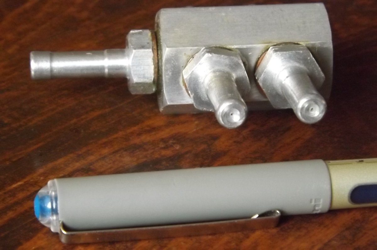
KGWilson, all good. And yes, the siting of the Rotax fuel pumps is less than ideal. I think there is sometimes a misunderstanding regarding the Zenith/Savannah return fuel line: I come across references to it as 'returning excess fuel' or 'limiting excess pressure' but the orifice is so small (0.4 or 0.5mm, see pic) it will do neither of those things. I believe the purpose of it is to reduce the likelihood of vapour lock, as described. As to where or not it is 'necessary', for the cost of a couple more fittings and a run of pipe I would think it an excellent innovation. (PS my prestart routine includes: *Turn on aux fuel pump, observe pressure rise to > 2 PSI. *Turn off aux fuel pump, observe pressure fall to 0PSI to ensure fuel return orifice is not blocked.)

-
Okay, vapour lock. To consider that more closely (in the context of a non fuel injected engine) : Some of the pipework is full of vapour instead of liquid. And if this includes the main fuel pump, then the pump can get only limited traction, so we are now relying on gravity feed to push the vapour out via the carburettor float needle jets. Furthermore, if part of the pipe work is still hot, the arrival of liquid fuel may result in more vapour. In the case of the Savannah, the electric fuel pump is low on the LH firewall, receiving fuel from a line under belly of the aircraft. Some builders now prefer to site it behind or under the seats. Either way, it is well placed to receive and pump unheated fuel. Meanwhile, at (or just before) the carburettor end of the setup, the return fuel line mentioned above allows vapour to bleed out of the system and back to the tanks. This seems to me to be a pretty good system, in terms of reducing the likely impact of vapour lock situations.
-
KGWilson the Savannah fuel is gravity fed from the wings to a header, and via an electric booster pump to the engine. At the manifold where the fuel line splits to the 2 Rotax carbs, there are 2 other spigots with very small orifices: one goes to the fuel pressure gauge, the other is a return line, normally hooked to a high point in one of the wing tanks. On several occasions I have had the following scenario: Land on private strip, spot the owner, park up for a yarn. 15 or 20mins later, prepare to leave, activating the electrical fuel pump prior to starting. **Listen as the fuel pump runs very rapidly for 5 or 10 secs, then slows down as the fuel pressure rises.** Start engine, take time taxiing and prepping to allow cooling of engine compartment. Fly away. **What is happening at this point is that the the fuel in the pipework in the engine compartment has vaporised, the electric pump runs rapidly as this vapour is pushed through the return line orifice (or possibly to the carbs) then slows once the pipework is flooded. This rapid electric pump run only happens under the above circumstances, and I take it as a warning not to hurry my departure until I am confident the fuel system is delivering correctly.
-
Nice! I have a (non-aviation) story to add to all that: A friend of a friend is a successful rally and car race photographer, taking the sort of action pics that end up in magazines, calendars and ads. At one stage he was also commissioned to take static pics of lovely ladies draped across hot vehicles, and found himself having to source various garments for the project. Including a pair of bright red stilleto thigh boots, bought very cheaply from a local big box store. On completion of the shoot, he and his wife put the surplus costumes on TradeMe (which is our Ebay). And the bright red stilleto thigh boots caused a bidding storm, eventually selling at multiples of the original purchase price. So they bought some more. And the same thing happened. And so far as I know, they carried on like this until the big box store finally ran out of stock...................
-
Does the Jab have a return line bleeding fuel back from the engine compartment to one of the tanks?
-
Skippy, so far as I can make out on the two ported bar that is swung forward at approx 45deg: The upper port is in the upper sloping face but is drilled back horizontally (not perpendicular to that face). The lower port is in the in the bar end, which is angled down at approx 45deg , and is drilled perpendicular to that end. As for the Dynon, the pitot port is at the front tip of the probe in the usual manner, while the other port is part way under the rounded tip, so set in a surface that is angled down. There must be many ways to manufacture a pair of pitots ports, one pointing forward, the other angled downward, which is the aim of the exercise. I have chosen to use a bar for ease of fabrication and mounting, and not to have it swung forward, as I am wanting to use an existing hatch for mounting, while maintaining the port position back under the wing as recommended.
-
Skippy, as I see it: 1. How the pitot ports are formed.......solid bar/tube/drilled rivet........is immaterial, provided that they are in clean air and not affected by surrounding structures. 2. After that, you are looking to maximise the change of pressure as the angle of attack shifts from approx 0deg to 20deg: the greater the change, the better the accuracy and resolution of the reading will be. 3.Various manufacturers appear to set the second port at between 45 and 60degrees. I believe they do this to optimise the accuracy of their equipment. Setting the second port outside this range (or mounting it elsewhere) may result in a less accurate reading.
-
Skippy, if I understand you correctly, you are proposing to implement the Dynon imminent stall option, but with a DIY second pitot setup, rather than with the Dynon head? If that is the case, I would be looking to emulate the Dynon head in some way: that is, I would have the second downward tilted pitot close to the forward facing pitot, and at something like the same angle as the Dynon: there are plenty of pics of their head, which show the position and angle. This should be easy to arrange with a short length of pipe, or similar. And in my view it would be most likely to give a good match to whatever filtering and calculation is built into the Dynon system.
-
PS: I believe Dynon offer a 2 port pitot head which then enables their A of A option. They make good gear, so I would expect it to work well. However, the readout is (I think) down with the rest of the glass cockpit stuff, which is not where I would want my eyeballs on finals. The audio system mentioned above is a possible workaround for that. It will be interesting to see how well that works in practise.
-
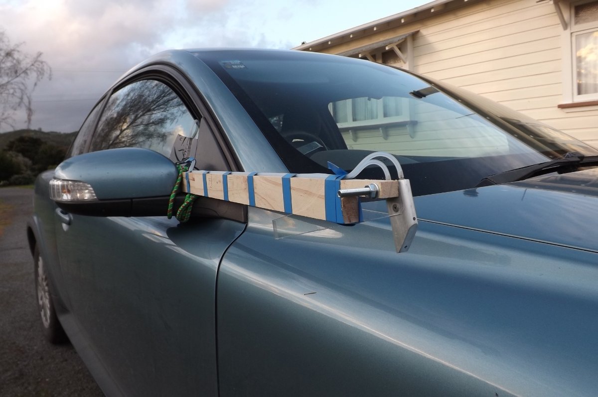
Hi Skippy. Don't be too tough on yourself: I printed the thing out, and digested it by slow and painful degrees! The guts of it are in the conclusions on Page 39, though this takes some interpretation too. My reading of it (in no particular order): 1. Two pitots, one faced forward, the other down at 45deg, were attached to the underside of the wing. The probe they used is shown on Page 7. I would guess the two pitots or ports are approx 100mm below the wing skin. 2. It is recommended that these be mounted between 25% and 60% of the chord of the wing, from the leading edge. 3. The ratio of the pressure readings from these two pitots can be used to calculate an accurate angle of attack. 4. This works at whatever the ambient pressure is: there is no need to correct for density altitude. 5. This works regardless of aircraft speed. 6. The results are relatively linear. 7. Calibration is required for the specific aircraft. There is a bit of work in it, and if what you principally want is a stall warning, there are probably simpler ways to come at it. I'm finding it an interesting project. I have put in a fair bit of work to filter the readings from the two ports in order to give a clear (non-jittery) readout, but with minimal time lag. It's been on the back burner with extended family visits here, but I hope to get back into it soon. Here is a pic of my Mk1 probe, lashed to the Volvo for ground testing. The neighbours took to twitching the curtains as the wife and I made numerous runs up and down the street at various speeds and various pitot angle settings...........)