IBob
-
Posts
3,012 -
Joined
-
Last visited
-
Days Won
26
Content Type
Profiles
Forums
Gallery
Downloads
Blogs
Events
Store
Aircraft
Resources
Tutorials
Articles
Classifieds
Movies
Books
Community Map
Quizzes
Videos Directory
Everything posted by IBob
-
Old K, mine are Taiyo Seiko THR-11 from Koyo Industries, still going after 40years. Japanese, and they still make exactly the same model. Highly recommended. Someone else may have to work out how to source them in Oz.
-
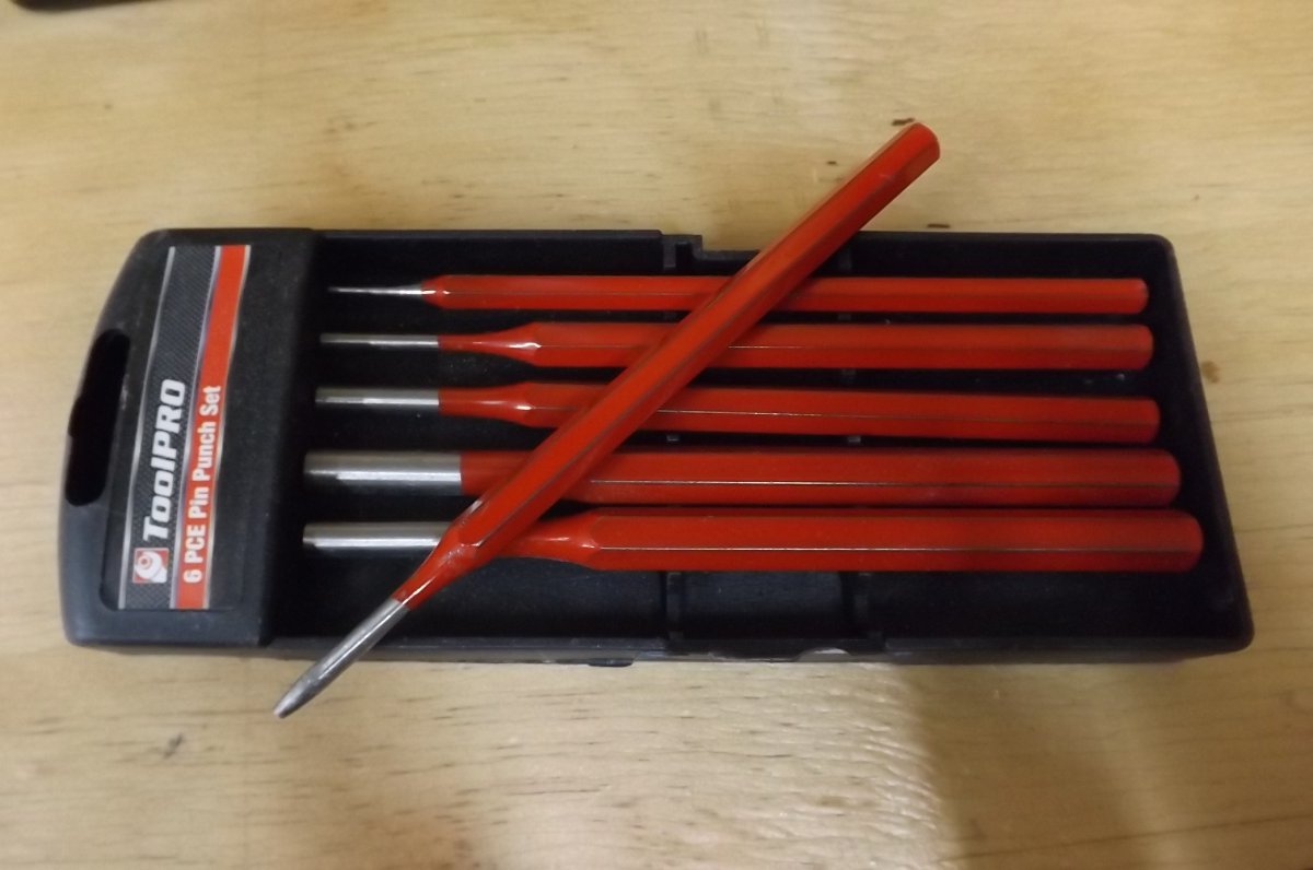
Just to be clear here: I agree entirely with Dan that holes can easily be damaged by using podgers. So, like many tools, they need to be used with a degree of 'feel', and avoiding any real force. To avoid damage, I also think they should be correctly shaped. 'Whatever is handy that fits in the hole' isn't good enough: The ones I used are tapered, with the thickest part a larger diameter than the rivet hole: when inserted, they are a snug fit in the hole, bearing on the hole all round and so helping to avoid damage at any one point round the hole. They are also polished, minimising any binding in the hole. For the A4 rivets, I was able to buy cheap tapered awls online. For the A5 rivets, I made my own by sanding a taper onto punches then polishing with fine emery paper. I had two of each and usually used them in pairs 'walking' them along a row of holes to bring them into alignment. I used them a great deal, and would strongly reccomend buying or making something similar. Below: an old awl and upholstery needle that didn't work well, and the two A4 awls that did. And a pin punch, sanded to a taper ready to be polished. When I realised how useful they are in pairs I made a second one of these too.

-
Hi Microman. For podgers I used tapered awls for the A4 Rivets and pin punches ground then polished to a taper for the A5 rivets. The podger does need to be a good fit in the hole, to avoid damage: hence the taper. In areas that were difficult to get lined up, I often found that 'podgering' in a different order worked: if it won't stitch together in one direction, try it from the other direction. I had no trouble with the undercarriage brackets: I believe the trick there is to work out why they won't fit, rather than try to force them. In my case it required a minor enlargement of the rectangular hole in the fuse side to clear the weld of the brackets (but obviously still leaving plenty of metal round the bolt holes!) They then just went in. This applied to one or two areas, notably the seat pans: don't force it, sort out the fit. At no point in my build did I put a drill through.
-

Warbird gathering video - Aviation porn.
IBob replied to red750's topic in Warbirds, Vintage and Classic Aircraft
Just wow.................that made my evening............) -
Turbo, Onetrack chose to edit his post. Why are you republishing something he chose to remove?
-
Skippy, the traditional fix here seems to be tape across the face of the radiator...though I did see a S Island build recently where they looked to be incorporating the oil cooling into the coolant circuit with some sort of plate heat exchanger, so requiring only one radiator. My preference (at this stage) would be for a ground-adjustable blind on the radiator that I can set without lifting the cowl. The trick would be coming up with something secure, durable and rattle-free. I haven't given the design much thought at this stage............
-
Skippy, I agree with you entirely when it comes to KISS: I made a living (though sadly not a fortune) specing and programming deliberately low tech high reliability automation. And it's part of why I didn't fit the oil thermostat yet. The other part is that I'm pretty sure if the unit failed, it would fail closed (as it's operated by some sort of capsule containing a wax that expans when heated). Which is the opposite of what you'd want. It's a Mocal OT/1-92 automotive unit. Next time the lid is off the factory Savannah here, I'll get details of the unit the Italians are fitting.
-
RFGuy there is a bit of extra pipework involved in fitting an oil thermostat: it's (obviously) not like a car coolant thermostat that just sits in circuit and throttles flow until temperature comes up. I saw Mark Kyle comment here earlier that he had a coolant thermostat fitted to his 912. It would be interesting to know what results that gave.
-
RFGuy, in the 912, oil is drawn from the tank, through the radiator, to the pump. (The oil temperature sensor is located at the pump.) From the pump, the oil is passed to the necessary places in the engine. The oil then pools in the bottom of the engine, and is pushed bank to the tank by crankcase pressure (blow by). An oil thermostat bypasses the radiator when cold, so that (some) oil is drawn directly from the tank to the pump, and on to the engine. In installations I have seen, it sits neatly in the upper area behind the gearbox.
-
RFGuy it's pretty slow in cooler weather. Not that it's something that annoys me. I do have an oil thermostat I bought from SA a while back, but have never got round to fitting it. I would think it would make a difference, though I also remember reading some comments a while back (on this site, perhaps) saying it didn't make much difference, and speculating that the oil tank was also acting as a radiator. I saw under the hood of a factory build Savannah recently and it had an oil thermostat. I don't know if they are now part of the package, or an optional extra.
-
Skippy, I can't say I'd thought much about radiator sizes, but I guess it's a matter of what works within some constraints of where you can put it? While I'm not privy to the ICP design process, at a guess I would say that when they remodelled the cockpit and nose and went from motor bed to ring mount (for the XL which went on to become the S) they probably sketched up a cowl, then worked out how best to pack in the necessary bits. And it's come together pretty neatly, including the airbox. The coolant overflow bottle is tucked way down in the back, but there's an easy workaround for that (thread fine neoprene tube down the bulkier overflow tube to add or remove coolant). As mentioned, there are questions in some quarters around the muffler, but it works okay on the large number of builds since then.
-
As for the installation, I went through a heap of cable ties, running and rerunning stuff until I was happy with how it all sits. It took a while. A lot of where to run the various bits, and just how to secure them at various points against vibration and chafing, came from studying pics provided by the (Australian) agent who supplied the kit. I found these invaluable in all sorts of ways as the build proceeded. I would encourage anyone building to source as many pics as they can to reference this sort of thing. In my case, I had an old laptop in the workshop, allowing me to view the agent's pics, also access pics on the site and other places.
-
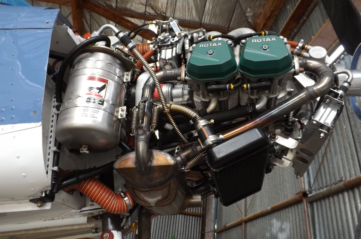
Skippy, what you see there is (or was) all standard ICP Savannah issue. The lower black radiator is coolant. The upper silver radiator is oil. Both these radiators hold the temps within specs within the ICP cowl design. I do blank off part of the oil radiator in winter, but all the radiator is required in summer. The metal hose also came with the kit. It's used for oil, coolant and parts of the fuel system. I know there is some debate about it, but I figured if it was failing in use we'd have heard about it. The downside (as used here) is that it requires a short piece of 'rubber' hose and two hose clips to terminate it. The upside is that it is very compact and can be hand formed into quite tight bends without any flattening or collapsing. At the engine, it allowed a very compact installation, especially for the larger 'hoses': I had heard the cowls were a tight fit, but this wasn't the case at all. The muffler is also ICP. It's compact and does the job, but various others have suggested it is a poor design, potentially reducing engine power. Also the muffler and downpipes don't fit together as neatly as they might, and a very competent LAME who took a look at it here made some scathing comments about the setup. I believe ICP may be working on a new design.
-
Interesting idea, RFguy, that's for sure. My 912 has run faultlessly since new, so I'm not actually looking for any sort of ignition problems. I'm just a bit surprised, now I'm focused on it, that there is nothing much to prevent the leads to the lower plugs from making contact with the metal of the cylinder heads. As you can see here, they are threaded through some sort of (heatproof?) white sheathing that just floats between the heads. All I did (at this stage) was pull off all the plug caps....and they were all tight.....put them back on, make and fit a couple of square grommets to hold the lower leads centred where they go down between the cylinders, and replace/adjust some cable ties on both upper and lower leads to try and ensure no contact with engine metal. (These are older pics, so not shown here).
-
That's certainly a possibility, Skippy. Unfortunately, since what I was trying to locate (radio interference cause) was something quite different to what I now have (smoother 'mag' check at 3000RPM) I wasn't focused on the latter. So I can't be absolutely sure now, but it seemed to me that rough running occurred with either 'mag'. Had it been notably one 'mag', I'd have gone looking for the cause.
-
As well as the preflight mag check, I am in the habit of running another mag check just before shutdown. This is something I got from another member here and the aim is to be confident that both ignition circuits are still working. (It's not a very good check, as the modules will be warm, but that's another issue). I normally do this post flight check at a lower speed of 3000RPM (instead of 4000RPM), and while my engine always ran on, it was noticeably rough during the mag check at this lower speed. I never thought much of it: I know the engine requires both ignitions for optimum firing and thought this just a symptom of less than optimum firing. Recently, however, I was chasing a minor radio issue I have (interference, but only at WOT) and started at the plugs and leads with the intention of working back. On inspecting the leads to the lower plugs, I found signs of rubbing where they pass down between the heads. There was no damage to the leads or outer sleeve, but it was quite obvious that they sometimes rubbed or vibrated against the metal of the heads : hardly surprising, as they are unsupported where they pass down through this narrow gap. In order to eliminate this as a possible cause of interference, I made a couple of square rubber grommets to guide the leads between the heads. I also inspected and/or replaced the cable ties on all plug leads at the heads, with the aim of keeping the leads away from the metal of the heads. The result of this is that (while I still have my WOT radio interference) my mag check at 3000RPM is no longer rough. So either removing and refitting all the plug caps has improved a connection (but they were all on tight when I removed them) or carefully routing the leads away from the metalwork has improved the ignition at this slower RPM.
-
You're welcome, Phil. While you're on it, there was a modification to the front strut wing attachment, you may want to check if you have that. I'm a bit hazy on the details (my S kit had it built in) I believe it's something fairly simple like a packing piece between the paired attachment points from the strut. JG3 or Mark of Kyle Communications, who both post here, would have more details.
-
Hi Philbtilly, the wings are so fat and rigid, I doubt you'd be able to induce any washout. I first fitted the wings to the fuse using the front fully assembled struts with the predrilled ends. I then fitted the rear struts complete with the undrilled end, marked for drilling, removed, drilled and refitted. And she flies just fine. The flaperons provide a sort of washout: the outer segment of each flaperon is offset upwards by a set measurement from the inner segment.
-
They make muscle-bound buses that like to drive past mirrors???
-
Nev, the coefficient of expansion of the coolant will be much higher than the coefficient of expansion of the metal of the engine. So when engine and coolant heat up, the coolant increases in volume more than the galleries in the engine, and since it is not compressible, has to vent somewhere. Same with a hot water boiler, they have an expansion vessel, usually sized 2 x 4% of the system volume, 4% being the expansion of water from approx 4deg to boiling. Without that you'd lift the safeties on the boiler each time it fired. If the Rotax had no venting, the damage would probably be to the hoses. What happens instead is that the level in the overflow bottle rises each time the engine is run up to temperature, and falls each time it cools. Or that's what mine has done, since new. I know this because initially I had a self-inflicted leak that took a lot of fixing (the engine, not me) and have watched my coolant level carefully ever since.
-
Hi Skippy, I don't disagree, but I think it's potentially dangerous to suggest using the overflow as a coolant indicator. Someone posted a link to footage of an EFATO here recently........was a Drifter or something similar, I think, Rotax 2-stroke....and some eejit had piped the overflow into the top of the bottle instead of the bottom. I expect that setup showed plenty in the overflow, as the engine progressively took in more air from flight to flight until the cooling failed entirely...
-
It's more usual to see a thermostat on the oil system, though I don't know if this is now a factory standard or option. Anyone?
-
Hi Skippy. Rotax moved from monitoring CHT to monitoring coolant a while back (2015?). As noted, the difference is in the heads: you either have sensors on the bottom (CHT) or top (coolant). You don't get to choose (unless you want to swap heads). All the recent 912 installations I have seen have the little sight glass in the front of the coolant reservoir. You can't check coolant level by looking at the overflow bottle: in the event of a coolant leak (for instance) you are quite likely to have good level in the bottle, but a lot of air in the coolant system.
-
So far as I know, the 912 does not have a coolant thermostat. Have you checked your coolant level? There is a little window in the coolant reservoir on the top of the engine, where all the hoses run to. With the engine cold, you should be able to see a coolant level there.
-
The earlier 912s had CHT sensors (on the underside of the heads), the later ones are not CHT but coolant temperature (sensors on the top side of the heads). The cylinders monitored are 2 & 3, which is front left and rear right. My 912 has the coolant temp sensor, and L appears to run a bit cooler than right, which makes sense as the L is a front cyl and the R is a rear cyl.