IBob
-
Posts
3,012 -
Joined
-
Last visited
-
Days Won
26
Content Type
Profiles
Forums
Gallery
Downloads
Blogs
Events
Store
Aircraft
Resources
Tutorials
Articles
Classifieds
Movies
Books
Community Map
Quizzes
Videos Directory
Everything posted by IBob
-
Mine rattles sometimes if taxiing, but I wouldn't describe it as slamming. On takeoff the usual thing is to get the weight off the nosewheel as soon as possible, but without premature rotation.
-
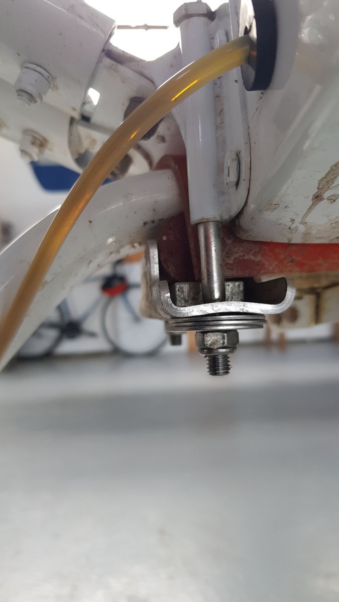
Skippy, that bottom plate has raised edges , to hold in place the bottom rubber under the UC. So a flat plate wouldn't do it. I think the source of the problem is the holes in the plate, they are slotted in the fore and aft direction, so weakening the plate and allowing it to dish up, as you can see in the pic. I guess they are slotted to allow for variations in the bolt positions, but I think the slotting is excessive. And it could have been done only for the rear bolt, which does not take the braking load. As it is I'm confident that the washers will prevent the bolts pulling through....not very elegant, but I want to be flying rather than tinkering. Oh, and I'll be less heavy footed with the brakes in future.......) Facthunter, the brakes come with the kit, and I suspect are made inhouse. The boys with the really fat wheels put bigger brakes on, and sometimes add a wire stay from firewall back to the lower UC to prevent the UC folding back under.
-
Facthunter, this is the main UC. It is clamped between hard rubber (lurethane?) over and under it. That is the red stuff in the pic. But hard braking or the like causes the wheels to pull back, and all that load is taken by the front mounting bolts.
-
The rollers are not (normally) loose, Facthunter. They have some rudimentary cage. And nothing stops the crud getting in, but it is in a relatively sheltered spot.
-
The main undercarriage is held in place by a steel plates underneath, secured by SS bolts to front and rear of the leg. I recently saw pics from a heavy landing where the UC had folded back under the fuselage. The steel plates have slotted holes, and the front bolts were intact but had pulled entirely through the plates. On examining my steel plates, I found they are now dished upwards, probably due to over heavy braking. A factory build on the airfield has 3 penny washers under the plate to prevent this, so it is not a unique problem, and I have now added washers to mine.

-
The nose leg is held down by a bungy. In that position (noseleg fully down) the bearing and it's associated washers are taking the downward thrust of the leg. Once sufficient load comes on the noseleg it telescopes upward and there is no load at all on the bearing. So all the bearing does is provide smooth rotation of the noseleg when taxiing and flying (since the nosewheel is linked to the rudder pedals for steering). There is little feel to the Savannah rudder pedals when flying, and the rudder is not fully self-centering, probably due to the friction of the bungy. I would guess the bearing was added to avoid further turning friction in the noseleg.
-
Nope, that's a new one. My only suggestion would be to check that you have the components stacked in the right order, as per Ch16 P8/11.
-
Neil I don't think it's a new idea at all. Just new to me.........😳 I think the tubes used are acrylic, but that thin pneumatic tube would probably work just as well, and would be more readily available.
-
I saw a clever manufactured one recently. It had a transparent tube about the size of a drinking straw, you dip it in then put your finger over the top end, draw it out and the fuel level stays in the tube to be read against the marked strip it is attached to. For now I'll fool around with what paints I have, see if I have anything that doesn't dissolve or flake when dipped in petrol. Worth a shot too, Marty, but I'm pretty sure the oil would wash out.
-
What sort of paint did you use, kgwilson?
-
On completion of my build, I made a dip stick for dipping the tanks. I made it from matai, which is a NZ native timber, reasonably dense, fine grained and resinous. I spent some time on it and was pleased with the results. However, it doesn't work as well as it might: the fuel wicks up the wood and I have to be quick and careful to see the wetted part, otherwise it is easy to get an artificially high reading. Is there some sealant that I could use to prevent the wicking? Alternatively, what would be a better material for making another one?
-
Some of the folk who fly them don't look too good either.......)
-
They are........that or Aircraft Spruce. And they are a very tight interference fit in the Rotax...I froze them, greased them lightly, then pulled them into place in the Rotax before mounting anything to them. So sort out the required bolts and spacers to pull them all the way in before going to the freezer...)
-
A note to add here: The ICP manual says to weigh for W & B with no fuel in the aircraft. You cannot fully empty the wing tanks with the aircraft sat level. Also just lifting the nose a bit (I had it on a bit of 4 x 2 so 2" high) does not renew the flow to drain the remainder, probably due to unavoidable undulations in the pipework in the wings. To fully drain the wing tanks. sit the aircraft back on it's tail.
-
Scroll to last entry here: https://www.rotax-owner.com/en/912-914-technical-questions/8008-fuel-return-line-for-a-912ul?start=10
-
Area51 I think you're missing my point: I'm not disputing whatever may have been quoted above, I'm wondering what size orifice they are using for that sort of flow. My Savannah has individual tank valving, but returns only to the RH inner. And I can guarantee that the return rate is not a fraction of the figure you mention.
-
Skippy has taken some actual measurements on orifice size vs flow.........where is he when we need him?
-
Area51 yes I know Rotax have a recommended return line orifice. But 2L a minute doesn't pass the reality test: that's about a cupful every 6 seconds, go fill a cup in 6 secs and you will see there is no way that volume could come out of such a tiny hole... Come to that, why would anyone design an engine that takes 17LPH in cruise, and circulate fuel at 135LPH???
-
FlyBoy certainly friction losses may be a significant element, though they are far more noticeable with higher flow rates. I believe the difference of pressure in separately vented tanks to be far more relevant: Eg: The fall from my fuel tanks to my fuel selector manifold is approx 250mm (the selector is on the RH baggage wall, where I can see it). Add approx 200mm for full tanks = 450mm which gives a fuel pressure at that point of just 0.49PSI So very small differences in upper tank pressure due to slightly different venting, prop swirl etc can result in proportionally large differences in fuel pressure from L and R. And that will only get worse as tank levels fall. Aircraft with floor mounted fuel selectors are marginally better off. In mine that would double the pressure at the selector, but certainly not enough to minimise the effects of unbalanced venting.
-
That seems to suggest the return line is delivering at a very high rate. I believe Skippydiesel did a fair bit of work recently with his return line orifice, and may be able to give us some rates from the various sizes he tried. As for uneven feed, I am told all aircraft suffer from this to some degree. I have been able to reduce this on my Savannah by doctoring the angle of the ends of the tank breather pipes. But if I was building again I would look at some means of cross-porting the upper tanks, with a single breather, as Cessna do. Having said that, I have seen some odd fluidics in industrial settings, where separate flows are siamesed together: sometimes the flow from one input would take over entirely, excluding flow from the other, though admittedly this was usually in much higher flow situations than an aircraft fuel system.
-
Assuming you want accurate weights (and in my view you'd be nuts not to) it starts with certifying or calibrating the scales. I checked mine with a range of certified test weights at a local industrial breadmaking business. After that you can either raise and lower a wheel onto the scales (I used a small hydraulic jack) with the other two wheels packed up (I put a strop across to prevent the UC spreading)....... Or you can roll the aircraft onto the scales, which is not as simple as it sounds unless you have nice big pads for the other two wheels and a good sized lead-in pad for the scales. In theory at least this gets you away from the problem of the main UC spreading and putting side load on the scales. I believe this is how it is normally done. However you do it, you need to take multiple weighings and they should deliver very consistent results. If that is not happening, something is wrong with your setup.
-
Further experiment and correction to above: Weighed self on flat, then weighed again with scales flat but leaning shoulder on slippery wall: this is closer to the Savannah situation, where the weight is on the wheel, but there may also be side thrust as the UC spreads. In this situation, the scales over-weigh. In both the above scenarios, the scales tolerated a small amount of tilt or lean without over or underweighing. How much probably depends on the design and construction of the particular set of scales.
-
Conducted minor experiment with digital scales: Weighed self on the flat, then placed scales on rigid board, chocked up at one side so scales are no longer hortizontal, and weighed self again. As the board is tilted up, the scales progressively underweigh. So unless something is done to ensure no lateral load on the scales, the scales will underweigh. Which could explain some of the unlikely low weights reported in other threads. In the case of the Savannah, if lifting and lowering the main UC wheels as I did for successive weighings, that means either preventing the UC from spreading when the wheel comes down, or arranging for the scales to move sideways, as Turboplanner did above. Or rolling on, provided that can be done smoothly.
-
 There is a Statement of Compliance in the very front of my build manual, with various details including MTOW of 1320lb. But that form applies to my specific kit and serial number, it's not generic.
 -
Lukeh, do you have the Pilot Operating Handbook that comes with the kit? Mine is Rev 5, Revision 05.12.2014 and on Page 24/44 it states MTOW of 600Kg (while noting that local regulations may limit flights to lower value).