Geoff_H
-
Posts
909 -
Joined
-
Last visited
-
Days Won
4
Content Type
Profiles
Forums
Gallery
Downloads
Blogs
Events
Store
Aircraft
Resources
Tutorials
Articles
Classifieds
Movies
Books
Community Map
Quizzes
Videos Directory
Everything posted by Geoff_H
-

Anyone using automotive cable for their starter motors?
Geoff_H replied to danny_galaga's topic in Engines and Props
Transmission lines have a steel core with aluminium strands around the outside. The aluminium strands are anodised to help them blend into the background to placate environmentalists. -
Anyone using automotive cable for their starter motors?
Geoff_H replied to danny_galaga's topic in Engines and Props
Just did some back of the napkin calcs ( if we can do it for the nbn we can do it for electrical cables). Ok this is just an interesting calc and many other issues come into play. I am not suggesting that this should be used for design, or poo pooing me😳. Units are not correct. For a given weight of 1kg the following resistances per square metre are: Aluminium 0.0011 Copper 0.0033 Iron 0.53 Silver 0.000163 Looks like silver leads for the starter motor (I am an engineer who said cost was an issue). But aluminium came in ahead of copper, now I know why transmission lines use aluminium, well there are other issues as well. -
Help Wanted (with metal fuel line plumbing)
Geoff_H replied to skippydiesel's topic in Aircraft General Discussion
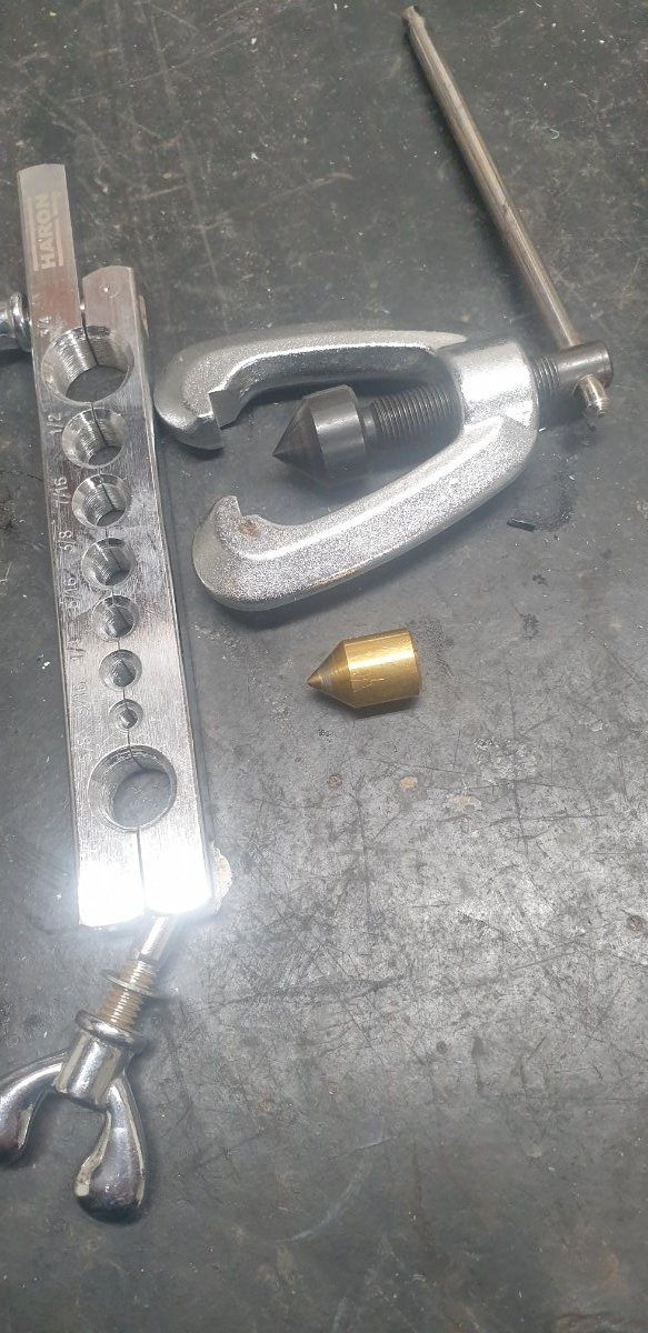
Actually no. The male forms the flare, even if it is fractionally out the nut forces the aluminium to shape. Done with this tool I have 100psi air from my aircompressor sealed. It uses anealed aluminium and blue alloy fittings. -
Help Wanted (with metal fuel line plumbing)
Geoff_H replied to skippydiesel's topic in Aircraft General Discussion
My homebuilt tool adaption seems to work for me. If you buy a standard Bunnings 45 deg I can make a 37 degree brass adaptor if you wish. -
Help Wanted (with metal fuel line plumbing)
Geoff_H replied to skippydiesel's topic in Aircraft General Discussion
Other size is 45 deg. A square can be used to find the angle on the fitting -
Help Wanted (with metal fuel line plumbing)
Geoff_H replied to skippydiesel's topic in Aircraft General Discussion
Skip I take it that your fittings are the 37 deg flare. I think that the blue aluminium fittings are. -
Help Wanted (with metal fuel line plumbing)
Geoff_H replied to skippydiesel's topic in Aircraft General Discussion
I have only single flared fuel lines. My 100 psi air line would benefit from double flare. One day I may make a tool for double flaring. What are others using on fuel lines? Maybe I should remake the fuel lines. -
Help Wanted (with metal fuel line plumbing)
Geoff_H replied to skippydiesel's topic in Aircraft General Discussion
Nice set of tools. The above set was made for copper. By making the adaptor piece o made the device work on Aircraft fuel systems including aluminium pipe and fittings. I made an adaptor system for my air compressor that uses aluminium tube and holds 100psi air. I like you set better, just like the cost of mine. -
Help Wanted (with metal fuel line plumbing)
Geoff_H replied to skippydiesel's topic in Aircraft General Discussion
My flaring tool. The brass piece is the substitute for aircraft angled flaring
-
Help Wanted (with metal fuel line plumbing)
Geoff_H replied to skippydiesel's topic in Aircraft General Discussion
I made an appropriate flaring tool and using a Bunnings gas lines and in the lathe made the end bit at the appropriate angle. I have made an aluminium line for my air compressor, it holds 100psi air. I will take pics and post them if anyone is interested. Geoff -
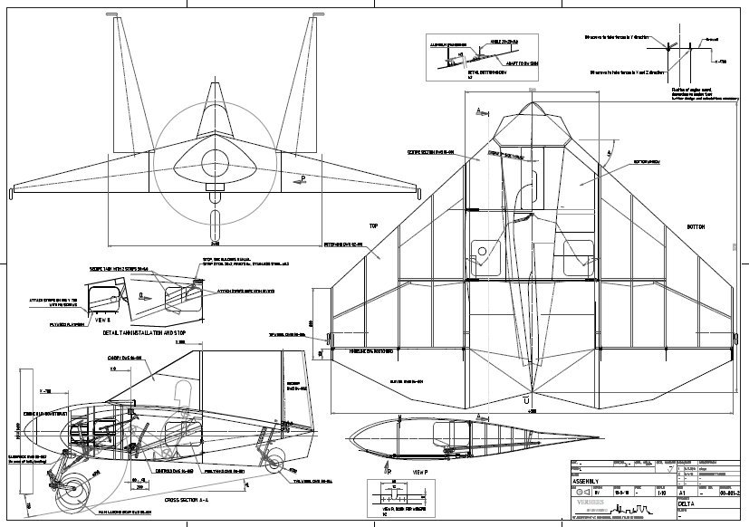
That is my concern. The spard seem very thick and angled, is their construction different This is the part where the designer talks about the stability of the design and some interesting differences to the "conventional design" https://www.verheesengineering.com/delta-aerodynamics/
-
Done that but the definition on the drawing has been lost. I actually know the wing span so I printed the drawing to fit on an A4 sheet, found the scale then scaled most dimensions. It is 8ft wide with wings folded up, found most other major measurements same way. So can guess the amount of aluminium needed, the website says "6061 or 2024" suggesting the craft could be made of 6061.
-
The Facitmobile second generation design uses flat panels, similar to stealth aircraft, however the for simplicity of design in this case. The designer had worked for a company that designed the early stealth aircraft. Delta wing aircraft are reported to be simpler with very large cockpit volumes.
-
Yes the D1 has a transparent floor to get better vision on landing. Tom Fink tried to teach me supersonic fluid mechanics, my results could have been better, but from what I remember subsonic and supersonic Delta wing design is very similar.
-
Did you notice the Concorde? Aerodynamics designed by an Australian, Prof Tom Fink, an absolute genius.
-
Posted email to him two weeks ago. No reply whatso ever. I have since been researching the internet dailey. Hence I am looking to this site.
-
I have been trying to get building information on this aircraft. I have searched the website but there is no information such as build materials, build time, pictures during construction etc. To buy plans to find out information would cost 400Euro. Id anyone building one or have a set of plans or bill of materials?
-
Anyone know contact information for John Corby
-
First flight for hydrogen powered testbed.
Geoff_H replied to red750's topic in Aircraft General Discussion
Gas turbines only require tweeking to run on hydrogen. In the fifties a flight with hydrogen on one engine was undertaken. I believe that aircraft running on hydrogen is the future. A cryogenic tank would hold the hydrogen, very similar to some rocket engines. On an off target issue hydrogen is the answer to overnight stored energy.- 1 reply
-
- 1
-

-
Aero Ex - Valkyrie 1 Design
Geoff_H replied to Peasant_Pilot's topic in Aircraft Building and Design Discussion
Looks great. -
Aero Ex - Valkyrie 1 Design
Geoff_H replied to Peasant_Pilot's topic in Aircraft Building and Design Discussion
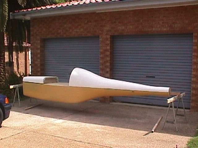
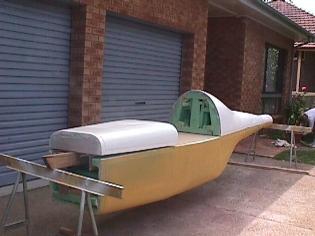
Those plugs were made by using the 3d autocad file to make 2inch slices through the cabin, print the slices full size, transfering the prints to particle board, then using foam (the florist style foam) sandwiched in between the particle board and sanding using particle board as guides. Long and laborious but effective. -
Aero Ex - Valkyrie 1 Design
Geoff_H replied to Peasant_Pilot's topic in Aircraft Building and Design Discussion
The Plugs that I made and a print of a view of the AutoCAD file. Geoff
-
Aero Ex - Valkyrie 1 Design
Geoff_H replied to Peasant_Pilot's topic in Aircraft Building and Design Discussion
Mooney have a steel frame around an aluminium skin in the pilot/passenger region. The tail is monocoque, the tail hinges off the steel frame to provide reduced drag trim. There are fewer deaths from Mooney accidents. -
Aero Ex - Valkyrie 1 Design
Geoff_H replied to Peasant_Pilot's topic in Aircraft Building and Design Discussion
I put 2 layers of Kevlar around the pilot area. It may have helped safety but took a huge toll on weight -
Aero Ex - Valkyrie 1 Design
Geoff_H replied to Peasant_Pilot's topic in Aircraft Building and Design Discussion
Somewhere I may have the 3D CAD files that I made, it was around 25 years ago. They were done in AutoCAD. I will have a look to see what has survived if interested.